
TIG Welding for Aerospace Fabrication: Precise Control for Thin-Wall, Critical Welds
A 0.035-inch aircraft tube doesn’t give you much room to correct a wandering puddle. Add a tight cluster joint, restricted torch access, and a drawing that controls weld profile, and you need more than a machine that can melt metal. You need control over where the heat goes, how much filler enters the joint, and what atmosphere surrounds the hot metal.
That’s where TIG welding earns its place in aerospace fabrication. Gas tungsten arc welding, or GTAW, separates the arc from the filler addition, so you can adjust each without automatically changing the other. It isn’t the fastest process for every aircraft component, but for thin sections, intricate assemblies, and many qualified repairs, that control makes it the best fit.
1. Independent Heat and Filler Control Protects Thin Aerospace Parts
TIG uses a nonconsumable tungsten electrode to establish the arc, with filler added separately when the joint requires it. On a thin-wall tube intersection, you can establish a puddle on the heavier member, bring the thinner edge into it, and add only enough rod to build the required weld. You aren’t feeding additional wire simply because you need more arc energy. That distinction matters when one edge wants to melt before the other gets moving.
Consider a 0.035-inch wall joining a 0.049-inch wall, roughly 0.9 and 1.2 mm. As you work around the intersection, the heat sink and torch angle change, so a current setting that behaves at the start may become too aggressive later. Remote amperage control lets you back off as the assembly gets hot. It doesn’t fix poor fit-up, but it gives you a way to respond before the root drops out.
- Arc length: A short, consistent arc concentrates heat; roughly 1–2 mm is a useful practice target where access and the procedure allow.
- Filler size: Thin sections may call for 0.030–0.045-inch rod rather than a large rod that chills the puddle with every dip.
- Termination: Controlled downslope and appropriate filler addition help avoid leaving a deep crater at the stop.
Those dimensions are technique examples, not an aerospace welding procedure. Production amperage, filler, joint preparation, and permitted manipulation come from the approved welding procedure specification, or WPS. The advantage is having the control to follow it.
2. Pulsed TIG Helps Manage the Puddle, but Travel Speed Still Matters
Pulsed TIG alternates between peak and background current, giving you another way to manage a small puddle. Peak current provides the energy needed to establish fusion, while background current reduces arc power between peaks. On thin stainless ducting, that can make the puddle easier to support and help establish a consistent travel rhythm. It isn’t a magic distortion switch.
For a practice coupon—not a production recipe—60 amps peak, 20 amps background, and 40% peak time gives an arithmetic average current of 36 amps. At 1–2 pulses per second, you can clearly see the cycle and coordinate your movement with it. Higher frequencies change puddle behavior and arc characteristics, but the result depends on the waveform, material, and technique. Average current alone doesn’t tell you the heat input because arc voltage and travel speed also matter.
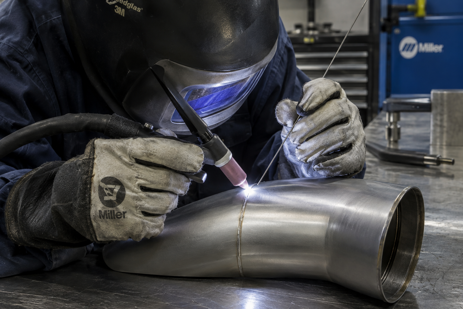
The trap is turning the current down so far that you have to crawl along the seam. You may get a wider heat-affected zone and more movement because you keep heating the same area. I’d prioritize repeatable fit-up, an approved tack sequence, sensible fixturing, and steady travel before chasing pulse settings. A cold-looking dial doesn’t guarantee a cool part.
3. GTAW Handles Aerospace Alloys—with Different Rules for Each
Aerospace fabrication includes stainless steels, nickel alloys, titanium, and weldable aluminum alloys, and TIG can handle all of them with the appropriate setup. That versatility is valuable in a shop handling ducts, brackets, tubing, and engine-related hardware. But “the machine welds it” and “the component is approved for welding” are two different statements. Material condition, filler selection, and postweld requirements still control the job.
Stainless, nickel alloys, and titanium
304L and 321 stainless, nickel alloys such as alloy 625, and titanium alloys such as Ti-6Al-4V are commonly welded using DC electrode negative. Their filler choices aren’t interchangeable, and matching the base-metal name isn’t always the correct selection. For example, some 321 stainless applications specify ER347 filler, while nickel-alloy filler selection depends on the particular alloy and service requirements. Use the specified classification and maintain its identity at the bench.
Titanium adds a much stricter shielding problem because hot metal readily reacts with atmospheric gases. The molten puddle, cooling weld, adjacent hot material, and root may all need protection. A shiny face doesn’t prove that the backside was protected. That’s why titanium technique starts with shielding arrangements, not just torch manipulation.
Aluminum needs oxide control and realistic strength expectations
AC TIG is commonly used for aluminum because its electrode-positive portion helps disrupt the tenacious oxide layer. For roughly 1.6 mm aluminum, a practice setup might use a 3/32-inch tungsten and an available current range around 60–100 amps, but joint design and heat sinking can move that requirement substantially. AC balance displays also vary: 70% electrode negative is not the same as 70% cleaning. Read what the machine actually displays.
Weldability also varies sharply by alloy. Welding 6061-T6 locally reduces its heat-treated strength, and 2024 and 7075 generally aren’t routine fusion-welding candidates for structural fabrication. A beautiful bead doesn’t restore the original temper. The engineering disposition has to account for that.
4. Clean Shielding Makes TIG Useful for Contamination-Sensitive Welds
TIG doesn’t normally use flux, and a properly controlled process produces very little spatter. That helps on aerospace hardware where cleanup access is limited and loose debris is unacceptable. Still, a clean-looking process can produce contaminated welds if the filler, tungsten, joint, or shielding system is dirty. Clean, clean, clean—and keep it clean after preparation.
Pure argon is a common shielding gas, although some qualified applications use other specified gases or mixtures. For a conventional #7 or #8 cup indoors, roughly 15–20 cubic feet per hour, or 7–9.5 L/min, is a reasonable practice starting range. Larger cups, trailing shields, and purge arrangements have different requirements. Cranking up flow indiscriminately can create turbulence and pull air into the shield.
- Prepare the joint: Use approved cleaning methods, dedicated tools where required, and clean handling practices.
- Keep solvents safe: Never use chlorinated brake cleaner around welding; follow approved solvent handling and drying requirements.
- Protect the root: Use the specified backing purge and provide an outlet so pressure doesn’t disturb the puddle.
- Verify protection: Follow procedure requirements for purge measurement, oxygen limits, and continued shielding during cooling.
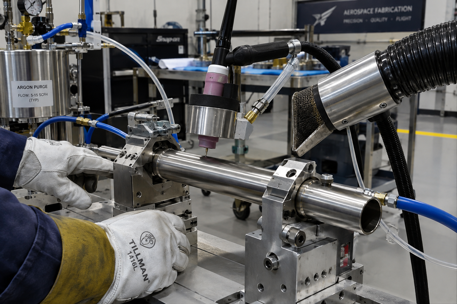
A gas lens improves gas distribution and can support extra tungsten stickout when the procedure and coverage allow it. That helps inside tube clusters, but it doesn’t make the gas column immune to drafts. Titanium discoloration is useful evidence of shielding conditions, not a complete acceptance test by itself.
5. The Right TIG Equipment Prioritizes Low-End Stability and Access
For thin aerospace work, I’d put repeatable low-current starts ahead of an impressive maximum-amperage number. A machine that starts consistently around 5–10 amps without an aggressive current surge can be more useful on delicate edges than one with extra top-end output. Check the specified starting performance separately for AC and DC. Then prove it on representative coupons.
A 200-amp AC/DC machine can cover many light-gauge fabrication tasks, while heavier aluminum or sustained production may justify 250–350 amps and more cooling capacity. Duty cycle needs checking at the current and AC conditions you actually intend to use. A 60% rating generally means six minutes of welding in a ten-minute period under the stated test conditions, not unlimited production because the front panel says “industrial.”
- Torch access: A compact #20 water-cooled torch suits sustained work in restricted areas; a #9 air-cooled torch can suit lower-current, intermittent work.
- Remote control: A pedal works well at a bench. A fingertip control may be more practical when the assembly dictates your position.
- Start and finish controls: Noncontact starting where permitted, preflow, downslope, and postflow help make the sequence repeatable.
- Electrode preparation: Use the specified tungsten type, diameter, and preparation, with dedicated grinding equipment to limit contamination.
My preference is the smallest torch that comfortably handles the required load. An oversized torch can force a poor angle, and then you spend the entire weld compensating for equipment that doesn’t fit. Access is a welding parameter in everything but name.
6. TIG Beats Competing Processes Where Flexibility Matters Most
TIG is especially compelling for short runs, variable joint geometry, thin tubing, and repairs explicitly authorized by approved technical data. You can see the puddle clearly and adjust filler placement without changing wire-feed speed. Manual TIG also adapts to awkward intersections without requiring a dedicated production cell. The tradeoff is labor time and dependence on operator skill.
- Versus MIG/GMAW: TIG favors fine manual control and small welds. Qualified GMAW procedures can offer much higher deposition rates on suitable larger structures.
- Versus laser or electron-beam welding: TIG tolerates more varied manual work. Beam processes can deliver narrow welds and low distortion, but demand suitable fit-up, access, equipment, and process control.
- Versus friction stir welding: TIG reaches joints that don’t suit a rotating tool and its reaction loads. Friction stir welding is highly effective for suitable aluminum seams.
- Manual versus orbital GTAW: Manual welding suits irregular geometry; orbital equipment can improve consistency on repeatable, accessible tube joints.
The verdict is specific: choose TIG when access, puddle control, alloy compatibility, and production flexibility outweigh deposition speed. Choose another qualified process when its geometry and production advantages better fit the component. Aerospace doesn’t award extra credit for doing everything with a torch in your hand.
7. Aerospace Weld Quality Depends on Qualification, Not Appearance
A uniform stack of dimes is not an acceptance criterion by itself. Aerospace welds may be governed by AWS D17.1/D17.1M, customer specifications, repair data, and drawing requirements, depending on the contract and component. Those documents establish the applicable qualification and acceptance requirements. Don’t substitute general shop experience for the controlling paperwork.
Before welding, verify the WPS revision, welder qualification scope, material identity, filler traceability, joint preparation, and inspection plan. After welding, visual examination may be supplemented by penetrant testing, radiography, or other specified methods. Those methods find different kinds of discontinuities, so one isn’t automatically a replacement for another. Even a smooth face can hide incomplete fusion.
TIG welding is the best choice for many aerospace fabrication jobs because it gives you direct control over a small, visible puddle across a useful range of alloys. That advantage becomes dependable quality only when the fit-up, shielding, procedure, and inspection support it. Get those right, and TIG gives you control where thin, expensive parts leave very little room for guessing.