TIG Welding for Off-Grid Fabrication: Build a Reliable 200-Amp Field Setup
TIG Welding for Off-Grid Fabrication: Build a Reliable 200-Amp Field Setup
TIG welding for off-grid fabrication comes down to three things: usable electrical power, shielding gas that stays over the puddle, and material you can actually get clean. A compact inverter handles the welding, but the generator, wind protection, and prep tools decide whether you make sound welds or spend the afternoon chasing porosity.
A 200-amp machine is a useful starting point for brackets, tubing, stainless assemblies, and light aluminum fabrication. That doesn’t mean every portable power source will run it at 200 amps. Here’s how I’d build the setup, including where TIG makes sense and where another process earns its ride on the truck.
1. Match the TIG Process to the Field Work
DC TIG makes sense for mild steel and stainless when you need controlled heat, clean starts, and small welds without spatter. Think 0.065-inch-wall tubing, stainless equipment brackets, or accurately fitted sheet-metal assemblies. Conventional aluminum TIG calls for AC output, so a DC-only machine isn’t the right purchase if aluminum repairs are part of the work. Buy for the metal, not the biggest amperage number on the box.
I’d favor TIG for parts you can bring onto a stable table and shelter from moving air. Muddy equipment, badly fitted joints, and heavy outdoor repairs usually point toward stick welding instead. A TIG/stick inverter gives you that escape route without hauling another power source. Unknown alloys, lifting attachments, and fatigue-loaded vehicle parts still require identification and an appropriate repair procedure; a pretty bead doesn’t establish that the repair is safe.
- Mostly steel and stainless: A 160–200-amp DC inverter keeps weight and power demand manageable.
- Mixed work including aluminum: Choose a 200-amp AC/DC inverter with adjustable AC balance.
- Long welds on thick aluminum: Expect greater power demand, torch heating, and potentially a larger machine.
2. Size the Generator from Input Demand, Not Welding Amps
A welder’s 200-amp output rating tells you very little about the generator it needs. Start with the manufacturer’s generator guidance and the input-current specifications at your intended output and supply voltage. For a North American setup, 240-volt operation generally makes full-output work more practical than 120 volts. Many dual-voltage machines substantially limit welding output on 120 volts.
Work through the input numbers
Suppose a machine specifies 28 amps of input at 240 volts for the operating point you need. That is 6,720 volt-amperes, or 6.72 kVA, before allowing capacity for other equipment. It isn’t automatically 6.72 kW because power factor matters, and a generator has both wattage and current limitations. Don’t substitute a lower duty-cycle-adjusted effective input-current figure for actual demand while the arc is running.
For that example, I’d investigate generators around the 9–10 kW continuous class, then confirm compatibility rather than treating that range as a guarantee. Use continuous output, not the larger starting-watts number, and check the actual 240-volt receptacle rating. A 30-amp receptacle still limits that connection even if the generator’s advertising suggests plenty of spare capacity. Grinder, compressor, cooler, and battery-charger loads all count.
- Voltage and frequency regulation: Both must remain within the welder’s specified limits under load.
- Waveform quality: Follow the welder manufacturer’s distortion limits; under 5% THD is a common screening target, not universal approval.
- Load response: Disable economy mode if the equipment instructions call for it or it causes poor response to welding loads.
Run a fuel-powered generator outdoors, away from doors, windows, and occupied shelters, with exhaust directed away from people. Never put it inside the welding windbreak to keep it dry or quiet. Neutral bonding, grounding, and GFCI arrangements depend on the generator and how it supplies the load, so follow the manuals and applicable electrical requirements. The work-return clamp completes the welding circuit; it isn’t protective equipment grounding.
3. Treat Battery Power and Extension Cords as Part of the System
Battery power stations can run some TIG equipment, but stored energy and inverter output are separate limits. A unit might hold enough energy for several small jobs yet trip immediately when you ask for a demanding weld. Check continuous output, surge behavior, voltage, receptacle capacity, and compatibility with the welder’s input load. Don’t assume two ordinary 120-volt outlets can be combined into a 240-volt supply.
For a rough runtime example, a 2 kWh battery with 85% usable AC delivery provides about 1.7 kWh. At an assumed 4 kW welding input, that works out to roughly 25 minutes of arc-on time, before idle consumption and other tools. Actual elapsed job time may be longer because you spend time fitting and cleaning. Solar can replenish energy, but a 400-watt panel isn’t directly supporting a several-kilowatt welding load.
Keep extension cords short, fully uncoiled, and sized for the load, length, connectors, and installation conditions. A long undersized cord causes voltage drop, and some regulated inverters draw more current trying to maintain output until they reach a limit. Follow the equipment’s cord guidance rather than grabbing whatever reaches. Hot plugs, damaged jackets, or repeated low-voltage faults mean stop and fix the supply.
4. Build a Windbreak Before Increasing Argon Flow
A steady breeze can strip shielding gas off the puddle even when your flowmeter looks fine. Start with securely anchored, flame-resistant welding screens arranged to block crossflow while maintaining ventilation. A roof alone won’t do it, and a sealed tent creates a different problem by trapping fumes and potentially accumulating argon. Shield the weld, not your entire breathing space.
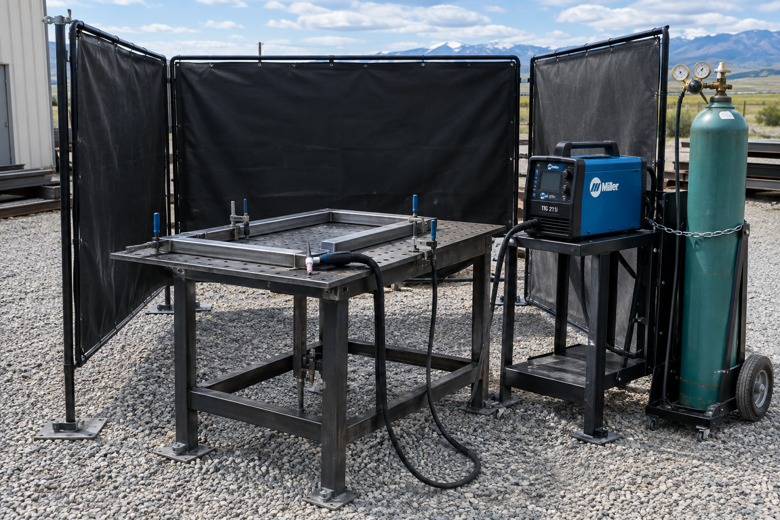
With a #7 or #8 gas-lens cup in sheltered conditions, 15–20 CFH of argon is a reasonable starting range. Cup size, tungsten stickout, joint geometry, and drafts can change what you need. A gas lens helps deliver a more even gas stream, but it doesn’t make TIG windproof. Cranking the regulator to 40 CFH can create turbulence and entrain air rather than fixing coverage.
A nominal 80-cubic-foot cylinder gives about four hours of gas flow at 20 CFH on paper. Preflow, postflow, purging, leaks, and unusable residual gas reduce the available welding time. Secure cylinders upright during use, protect them from impact and heat, and follow supplier and transport requirements when moving them. Check fittings with an approved leak-detection solution before leaving for a remote job.
5. Start with Settings That Suit a Portable TIG Setup
These ranges are starting points for practice coupons, not qualified welding procedures. Joint design, position, fit-up, travel speed, and the amount of surrounding metal can move the required amperage considerably. Set enough maximum current to establish a puddle promptly, then reduce it as the part heats up. Hanging around at insufficient current often puts more total heat into the assembly.
- Mild steel, 0.065-inch wall: DCEN, roughly 45–75 amps, with 1/16-inch tungsten and appropriately sized ER70S-2 filler for known, suitable base metal.
- 304L stainless, 0.065-inch wall: DCEN, roughly 40–65 amps, typically with ER308L filler; keep the arc short and avoid oversized beads.
- Mild steel, 1/8 inch: DCEN, roughly 90–130 amps, often with 3/32-inch tungsten.
- 6061 aluminum, 1/8 inch: AC, roughly 120–170 amps, with 3/32-inch tungsten; select filler for the alloy and service requirements.
Dial in AC without wasting power on cleaning
For clean aluminum, start around 70–75% electrode negative and 80–120 Hz AC frequency if your inverter offers those controls. Some machines display electrode-positive cleaning percentage instead, so read the balance definition before turning the knob. More electrode-positive time increases cleaning action but also heats the tungsten and reduces penetration efficiency. Remove oil first, then remove oxide with a dedicated stainless brush; AC cleaning doesn’t replace preparation.
A 2% lanthanated tungsten is a practical choice for carrying one electrode type for both AC and DC inverter work. Grind it lengthwise and prepare the tip according to the machine and electrode guidance rather than deliberately making a large ball for modern inverter AC. Start with roughly 5–10 seconds of postflow for moderate-current work and adjust for tungsten temperature and manufacturer recommendations. Keep the torch over the crater while that gas is flowing.
6. Pack for Torch Heat, Clean Metal, and Awkward Positions
A #17 air-cooled torch is convenient for lighter work, but its rating may be well below a 200-amp machine’s maximum output. Check the actual torch rating, including AC restrictions and duty cycle, because torch models vary. Sustained aluminum welding can make the handle and consumables uncomfortably hot even while the power source stays within its duty cycle. A #26 offers more capacity at the cost of bulk; a #20 water-cooled setup adds a cooler, coolant, hoses, and electrical demand.
I’d prioritize a flexible torch lead and a usable remote over extra menu features for field work. A foot pedal is fine at a table but awkward when you’re kneeling beside a frame on gravel. A compatible fingertip amperage control lets you change heat without balancing on one leg, although it takes practice to adjust without moving the torch. A trigger-only switch isn’t necessarily an amperage control.
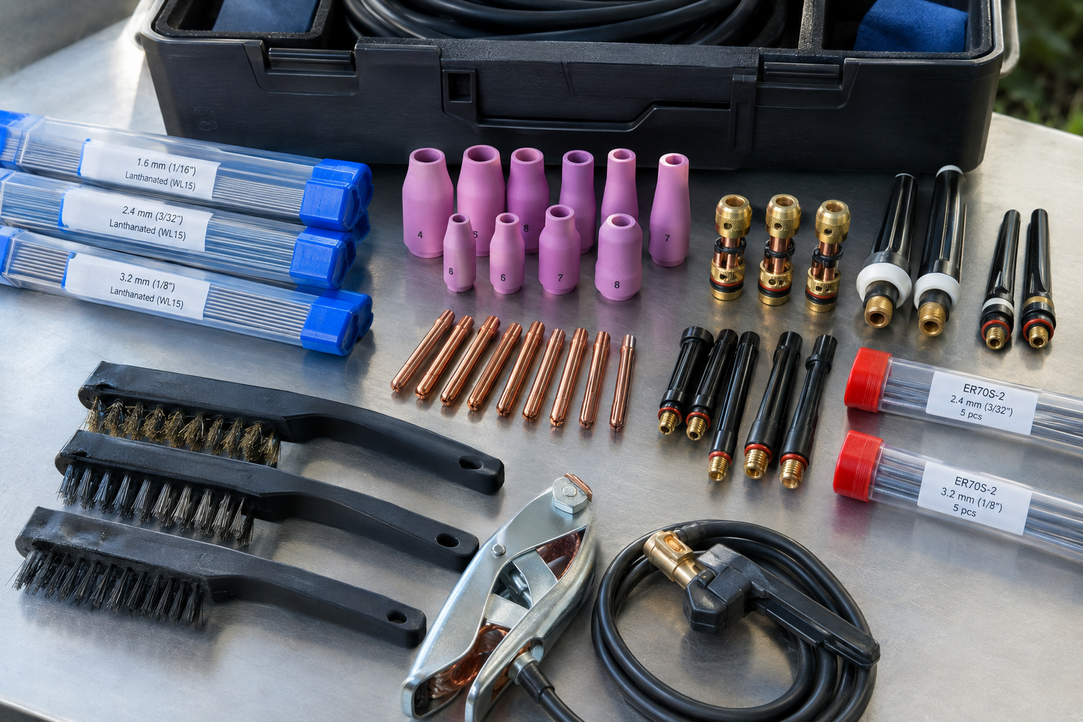
- Spare sharpened tungstens, cups, collets, collet bodies or gas lenses, and back caps.
- Separate steel and stainless cleaning tools, abrasives suitable for aluminum, and sealed filler storage.
- Suitable nonchlorinated cleaning solvent, used away from ignition sources and allowed to evaporate fully before welding.
- Clamps, squares, sacrificial tabs, and a reliable work-return clamp.
- Welding PPE, fire extinguisher, first-aid supplies, and an inspection light.
7. Prove the Setup on a Coupon Before Welding the Assembly
Run a scrap coupon matching the actual alloy, thickness, and joint before committing to the part. Test at the highest current you expect to use, with the same cord, generator configuration, gas flow, and torch. Watch for input faults, unstable output, tungsten oxidation, porosity, and excessive torch heating. This separates a supply problem from a technique problem before both get blamed on the machine.
Fit and tack the assembly with distortion in mind, then recheck dimensions before completing the welds. On a 30-by-30-inch stainless frame, welding one corner completely before securing the others can pull it out of square. Use a balanced sequence and appropriate restraint, and keep the return connection on clean metal close to the weld so current doesn’t travel through bearings or sensitive components. Don’t use the welding current to discover the available path.
Finally, inspect the welds and surrounding area before packing up, and maintain any required fire watch. Surface appearance alone doesn’t establish fusion or suitability for service. Reliable off-grid TIG welding isn’t about dragging the most powerful machine into the field. It’s about making the power, shielding, preparation, and technique behave like they do in a controlled shop.