
TIG Welding for Instrument Makers and Luthiers: Clean Joints Without Warped Hardware
A TIG weld on instrument hardware can look beautiful and still leave a mounting face crooked, a tube restricted, or a mechanism that won’t move freely. Small parts don’t give you much room to hide shrinkage. TIG welding for instrument makers and luthiers starts with choosing which joints actually belong under an arc, then controlling the heat closely enough that the finished part still does its job.
This is useful work for stainless brackets, fabricated tailpieces, steel fixtures, aluminum supports, and some titanium components. It isn’t a universal replacement for soldering or brazing. The trick is knowing the difference before you strike an arc on something expensive.
1. Choose TIG, Brazing, or Soldering Before You Prepare the Joint
TIG makes sense when you need a fusion joint in a known, weldable alloy and can tolerate some local shrinkage. A fabricated stainless mounting bracket is a reasonable candidate; an assembled brass instrument with soldered braces usually isn’t. The issue is that welding temperatures can damage nearby joints, finishes, and heat-sensitive components long before your new weld is finished. Start with the assembly, not the machine.
- TIG welding: Consider it for new steel or stainless hardware, weldable aluminum fabrications, and properly shielded titanium parts.
- Silver brazing: Often suits close-fitting sockets, lap joints, and mixed-metal components where melting the base metal is undesirable. Filler selection and joint clearance still matter.
- Soft soldering: Common on brass instrument assemblies designed for soldered construction and later service.
- Mechanical fastening: Prefer it where adjustment, replacement, or heat isolation matters more than a permanent joint.
Brass deserves a firm warning because zinc boils below the temperatures reached in an arc-welding puddle, producing fumes and encouraging porosity. Unknown vintage hardware may also contain lead or carry hazardous plating, so don’t grind it clean and assume you’ve solved the problem. Identify the material and coating before selecting a repair method. My preference is to reproduce a questionable small component in known stock rather than experiment on the original.
2. Match the Alloy and Filler to the Actual Instrument Part
Known stock saves more time than clever pedal work. For fabricated hardware, 304L stainless is straightforward to source and commonly welded with ER308L filler, while 316L typically pairs with ER316L. Mild-steel fixtures commonly use ER70S-2 or ER70S-6, selected for the base material and procedure rather than whichever rod happens to be on the bench. Don’t treat a hardened spring, tempered blade, or mystery cast fitting like ordinary mild steel.
Aluminum needs another decision because welding changes the properties of heat-treated alloys. You can weld 6061-T6 with a suitable filler such as ER4043 in many applications, but the heat-affected zone loses strength and doesn’t simply return to T6 by cooling on the bench. That matters around threaded bosses and highly loaded supports. It also matters cosmetically: filler and parent metal can look different after anodizing.
- Thin stainless sheet: Start practicing around 0.8–1.2 mm, or approximately 0.032–0.047 inch, before attempting delicate finished components.
- Filler diameter: Fine wire around 0.6–1.0 mm suits small steel and stainless puddles better than a heavy rod that chills the joint with every addition.
- Titanium: Match the filler to the grade and provide trailing and backside shielding wherever hot metal is exposed.
- Instrument springs: Welding can destroy their temper or create a brittle region; replacement is usually the better starting point.
A stronger-looking weld does not automatically make better acoustic hardware. Added mass, stiffness, and connection geometry can change how a component behaves, but there’s no universal “TIG tone” benefit. Keep the original dimensions and loading in view. The weld is only one part of the design.
3. Set Up a TIG Machine for Stable Low-Amperage Control
For this work, I’d prioritize a clean low-current start and predictable pedal response over a large maximum-amperage number. A machine rated to start at 5 amps can still give you an aggressive initial burst, so test it on scrap matching the job. DC electrode negative handles steel, stainless, and titanium; conventional aluminum TIG requires AC. A compact #9 air-cooled torch is often enough for intermittent small-part work and is easier to maneuver than a bulky torch.
Starting settings for representative practice joints
These are starting ranges for flat-position, close-fitting joints, not production procedures. Joint shape, clamping, backing, and travel speed can move the required current substantially, so establish a working setting on coupons first. Use the foot pedal to taper off as the part heats up. Don’t keep feeding the original current into a component that is now hot from end to end.
| Material and thickness | Process | Initial current range | Tungsten starting point |
|---|---|---|---|
| 304L stainless, 0.8–1.0 mm | DCEN | 20–40 A | 1.0 mm or 1/16-inch lanthanated |
| Mild steel, 1.0–1.2 mm | DCEN | 30–55 A | 1/16-inch lanthanated |
| 6061 aluminum, 1.0–1.6 mm | AC | 45–85 A | 1/16-inch lanthanated, within its AC rating |
- Shielding gas: Pure argon, initially around 10–15 CFH with a #5–#7 gas-lens cup in still air. Adjust for the actual coverage.
- Tungsten preparation: Grind longitudinally on a dedicated wheel; use a controlled point with a small flat appropriate to the current.
- Arc length: Keep it short, often around 1 mm on accessible thin joints, without touching the puddle.
- AC setup: Around 100–120 Hz and 65–75% electrode-negative time is a reasonable trial on clean aluminum if the machine allows it. Check how its balance control is labeled.
- Postflow: Begin around 5–8 seconds for low-current work and verify that the tungsten stays protected.
4. Fit and Fixture Small Hardware Before Adding Heat
A gap that looks harmless on a bench can become the entire puddle on 0.8 mm stainless. Aim for close, consistent fit-up, especially when considering an autogenous weld without filler. I’d rather spend another ten minutes fitting a bracket than bridge a wandering gap while its mounting holes pull together. Small parts reward boring preparation.
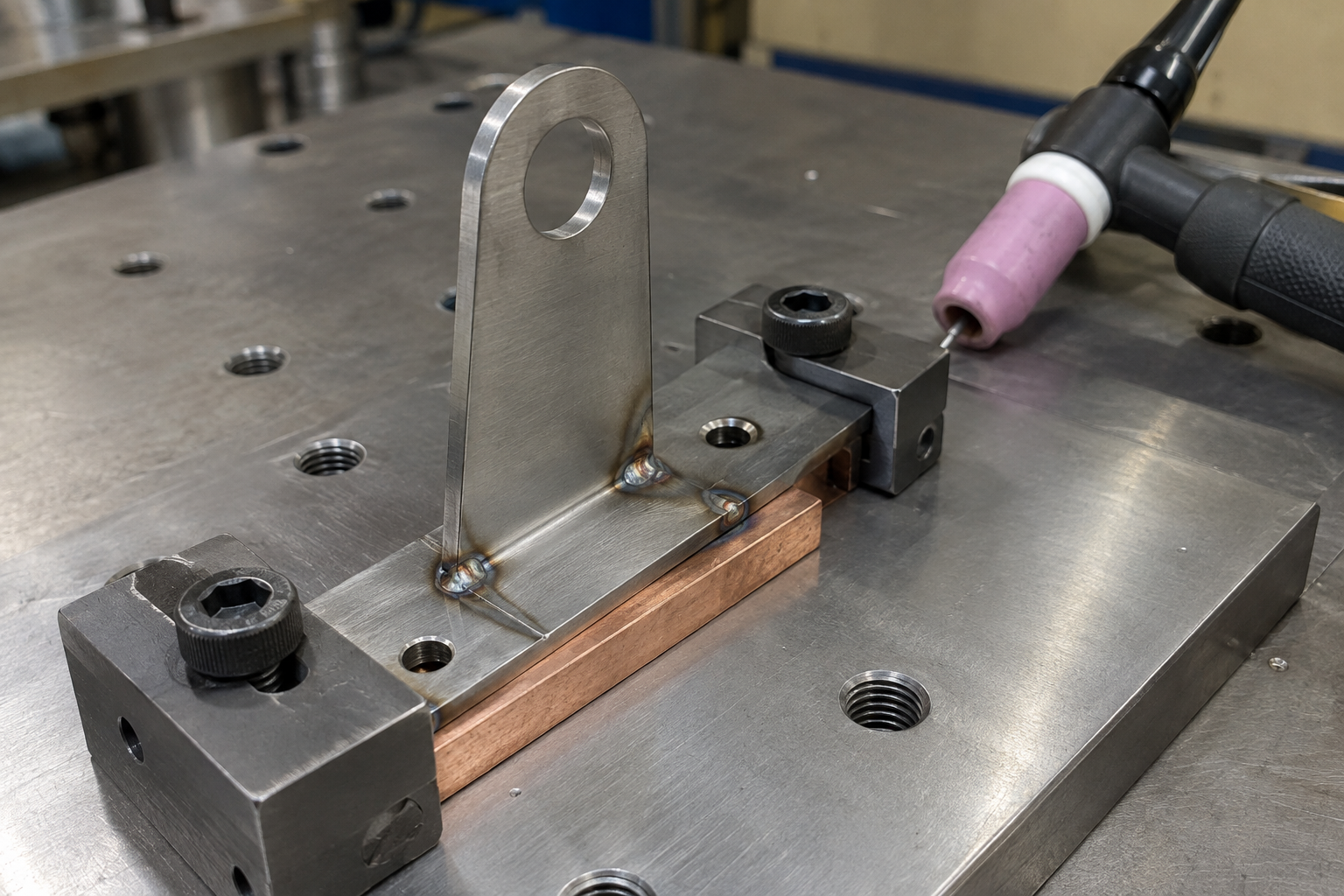
- Establish datums: Locate the mounting face, hole spacing, shaft centerline, or other surface that controls function.
- Provide backing: Use clean copper where accessible to support thin edges and pull away heat. Don’t melt it into the joint.
- Check access: Rehearse the torch angle and filler movement with your gloves on.
- Tack in opposition: Place balanced tacks, then recheck alignment before completing the joint.
- Plan removal: Don’t build a fixture that becomes trapped inside the welded assembly.
A fixture holds position, but it doesn’t cancel weld shrinkage. Excessive restraint can leave residual stress, and the component may spring out of alignment when released. Leave machining allowance on critical bearing seats or mounting faces when the design permits. For precision hardware, “weld, then finish-machine” is often the honest plan.
5. Control the Puddle Without Cooking the Whole Component
Thin instrument parts usually get into trouble through accumulated heat, not one spectacularly wrong pedal movement. Establish the puddle promptly, add only the filler the joint needs, and travel rather than sitting there washing the bead wider. Use short, balanced runs where the design allows, pausing between them for the component to cool. A tiny bracket can become fully heat-soaked surprisingly fast.
Use pulse for a specific problem
Slow pulse around 1–2 pulses per second can give you a rhythm for advancing and adding wire. Try background current around 25–40% of peak and peak time around 30–50%, then adjust against actual fusion and bead shape. These percentages don’t guarantee lower heat input if you compensate by crawling along. Pulse is a control tool, not an excuse to ignore travel speed.
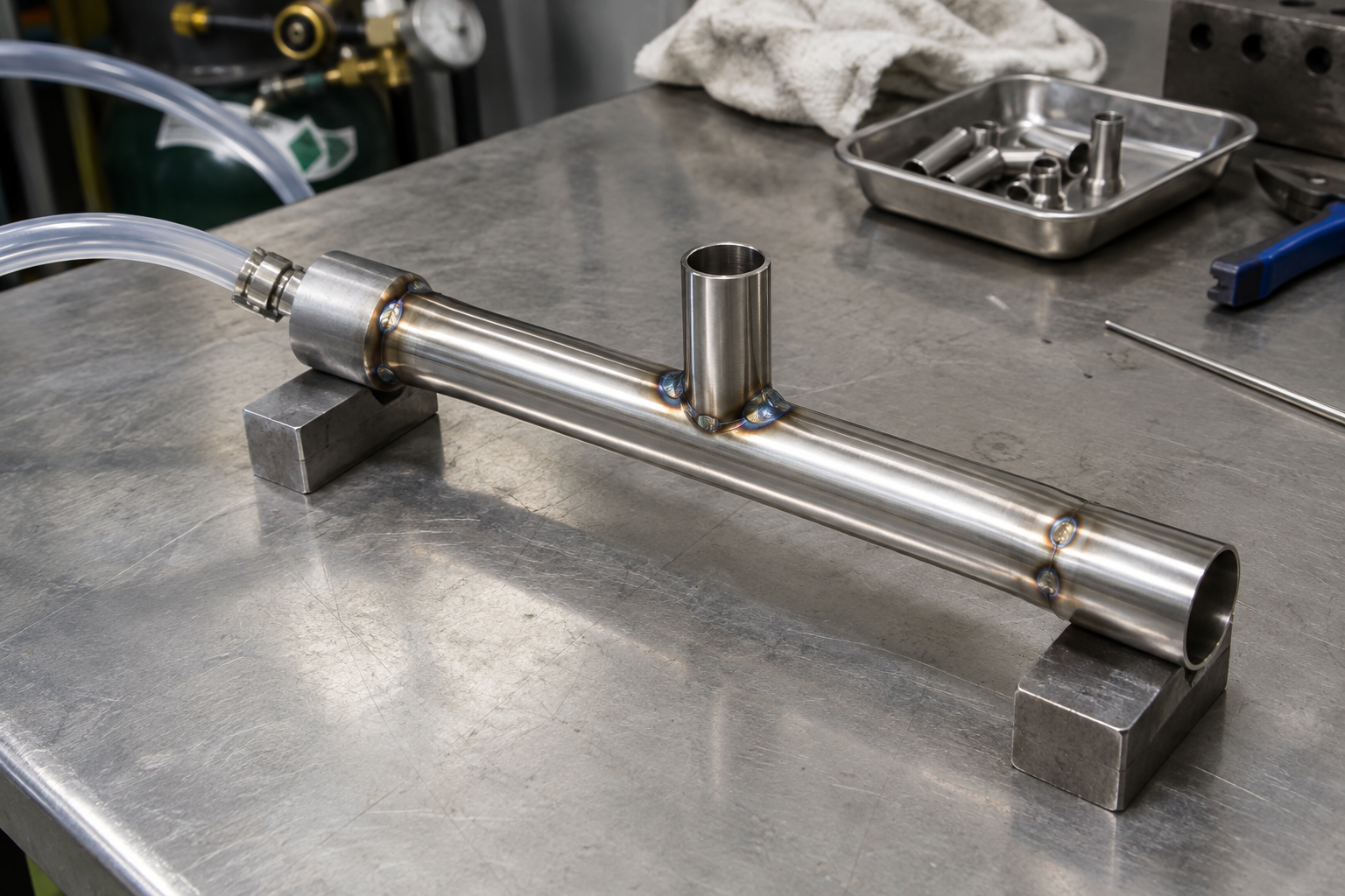
For thin stainless tubing, protect the root with an argon purge when the inside reaches welding temperature and is exposed to air. Heavy root oxidation, often called sugaring, leaves a rough, compromised surface that may be impossible to clean inside a narrow bore. Provide a purge outlet and use gentle flow rather than pressurizing the tube. Never weld a sealed cavity.
6. Keep Welding Heat and Contamination Away From the Instrument
Remove the component from the instrument whenever practical. Wood, lacquer, shellac, glue lines, felt, cork, pickups, and wiring have no business sharing the immediate welding area. A reflective shield doesn’t stop heat traveling through a metal bracket into a finished soundboard. If you cannot isolate the part, reconsider whether welding is the right repair.
- Work connection: Attach the work clamp directly to clean metal on the isolated component, close to the joint. Don’t route welding current through bearings, strings, or mechanisms.
- Electronics: Remove sensitive electronics from the welding setup and follow equipment guidance on high-frequency interference.
- Cleaning: Use an appropriate nonchlorinated cleaner, allow it to evaporate, and remove containers before welding. Never use chlorinated brake cleaner.
- Fume control: Use suitable local extraction without disrupting shielding gas; stainless welding fumes require control even when the bead is small.
- Shop separation: Clear wood dust, solvent vapors, polishing residue, and combustible waste from the welding area.
Unknown plating is a stop sign, not a sanding assignment. Nickel, chromium, cadmium, and underlying coatings require identification and an appropriate removal and exposure-control plan. Welding PPE and screening still apply at low amperage because a small arc can injure eyes and skin. Delicate work doesn’t mean harmless work.
7. Inspect Fit and Function Before Polishing the Weld Away
Check the component after it has cooled and been released from the fixture. Measure mounting-hole spacing, flatness, and shaft alignment before polishing, because a shiny surface can hide the evidence you need to troubleshoot distortion. Look for undercut, pinholes, crater cracks, and incomplete fusion at the toes. A tidy bead isn’t proof of a sound root.
On a new part design, section or destructively test a representative practice joint to check penetration and fusion. For thin tubing, inspect the bore with suitable lighting or a borescope where access allows. Dress welds only to the required contour, leaving enough section to carry the load rather than grinding everything flush by habit. Aggressive blending can turn an adequate joint into a thin spot.
Finally, assemble the mechanism and check its travel, clearances, and load path before it goes near a finished instrument. Remove stainless heat tint by a suitable controlled process, then clean and passivate where the service requirement calls for it; passivation alone doesn’t remove heavy oxide. The target is a sound joint, correct geometry, and no new service problem. The instrument doesn’t care how pretty the stack of dimes looked on the bench.