How to TIG Weld Thin Wall Tubing Without Burning Through or Pulling It Out of Shape
How to TIG Weld Thin Wall Tubing Without Burning Through or Pulling It Out of Shape
Thin wall tubing gives you very little time between a useful puddle and a hole. The fix isn’t simply turning the amperage down, because a lazy arc can make you linger until the whole joint gets hot and drops out anyway. You need close fit-up, enough current to establish the puddle quickly, and somewhere comfortable to put your hands.
This guide focuses on manual TIG welding of roughly 0.028–0.065-inch-wall tubing, especially mild steel and 304L stainless, with separate setup notes for aluminum. These are practice starting points, not a substitute for a qualified welding procedure on structural, pressure, sanitary, or other code-controlled work.
1. Fit the Tubing Before You Touch the Amperage
A gap that looks harmless on plate can swallow the edge of thin tubing. On a 0.035-inch wall, a 0.020-inch gap is already more than half the material thickness, so you’re asking the filler to bridge a considerable opening. For thin-wall butt joints and coped tube joints, aim for uniform contact without forcing the parts together. Don’t assume you can fix a poor notch with pedal control.
- Square butt joints: Cut the ends square, deburr the inside and outside, and check alignment around the entire circumference.
- Coped joints: Fit the saddle against the actual mating tube. A good fit on top doesn’t help if there’s daylight underneath.
- Edge preparation: Thin walls generally don’t need a bevel unless the procedure specifies one. Don’t grind the edges into knife points.
- Cleaning: Remove oil, paint, plating, mill scale, and marker residue from the weld area and nearby surfaces, including the inside where accessible.
Use abrasives reserved for stainless when working on stainless, and clean aluminum with a suitable degreasing method before brushing off oxide with a dedicated stainless brush. Let approved cleaning solvents evaporate completely; never use chlorinated brake cleaner around welding. Wear proper welding PPE and use ventilation or local extraction that doesn’t strip away your shielding gas. Stainless fumes and coatings deserve particular attention, even when the weld itself is small.
2. Set Up a Small, Stable TIG Arc
For mild steel and stainless tubing, start with DC electrode negative and 100% argon. A 1/16-inch, 2% lanthanated tungsten is a practical choice across much of this thickness range, sharpened lengthwise to a consistent taper with a tiny flat at the tip. A #6–#8 cup with a gas lens gives useful coverage without making the torch unnecessarily bulky. Start around 12–18 CFH indoors, then adjust for cup size, stickout, and actual shielding conditions rather than turning the flow wide open.
Starting amperage for thin steel and stainless tubing
The ranges below are reasonable pedal-limit starting points for close-fitting joints on roughly 1-inch-diameter tube. They aren’t instructions to hold full pedal all the way around, and a heavily clamped joint may need more current than a small, unsupported assembly. Practice on matching scrap and adjust until you can establish fusion promptly without washing away the edges. Stainless will often need less current than comparable mild steel.
| Wall thickness | Approximate thickness | Starting DC current limit | Useful filler diameter |
|---|---|---|---|
| 0.028 inch | 0.7 mm | 20–40 A | 0.030–0.035 inch |
| 0.035 inch | 0.9 mm | 30–55 A | 0.030–0.045 inch |
| 0.049 inch | 1.2 mm | 40–70 A | 0.035–0.045 inch |
| 0.065 inch | 1.65 mm | 55–90 A | 0.045–1/16 inch |
Use filler appropriate to the alloy and service: ER70S-2 is common for mild steel, and ER308L is typical for 304L stainless. I prefer smaller filler on the lightest walls because a big rod can chill the puddle enough that you chase it with more pedal. For aluminum, use AC and a separate test setup; 0.049–0.065-inch wall may need roughly a 60–100 A pedal ceiling, depending heavily on joint geometry and heat sinking. On an inverter, 70–75% electrode negative and 80–120 Hz are useful initial AC settings, but check whether your machine displays balance as cleaning or penetration.
3. Back-Purge Stainless Before Making the Root
When a stainless tube weld penetrates through the wall, the inside needs shielding too. Without it, the hot root can oxidize into the rough, dark surface welders call sugaring, compromising corrosion resistance and leaving a poor internal surface. Outside shielding won’t reliably protect the back of a full-penetration joint. Purge before tacking if those tacks penetrate through.
- Use clean purge dams or suitable caps to isolate a manageable volume.
- Provide an argon inlet and an unobstructed outlet that lets the existing air escape.
- For a small isolated tube section, roughly 5–10 CFH can be an initial purge-flow trial; reduce to approximately 2–5 CFH during welding if adequate shielding is maintained.
- Verify purge quality with an oxygen monitor when the application requires controlled root quality. Follow the specified oxygen limit rather than assuming a fixed purge time is enough.
The objective is to displace air, not pressurize the tube. Excess internal pressure can push against the molten root, so never weld a tube assembly completely closed without a safe vent path. Keep the purge running through welding and the required cooling period. Argon can displace breathable air, so don’t discharge it into pits or poorly ventilated enclosed spaces.
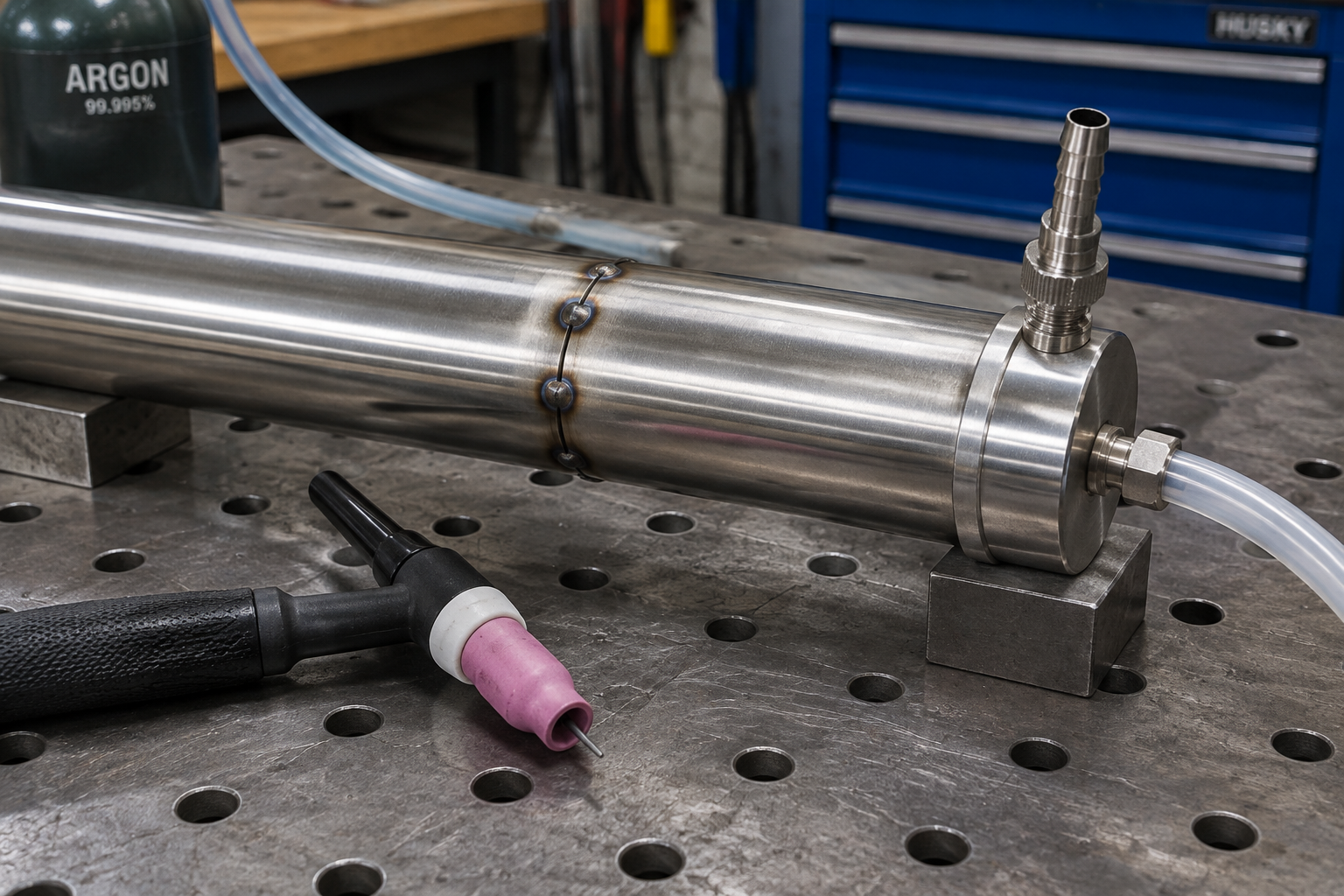
4. Tack in Sequence and Check Alignment Again
A tube joint can move noticeably after the first tack, especially if the ends weren’t sitting together naturally. On a small butt joint, four tacks at roughly 12, 6, 3, and 9 o’clock are a useful starting sequence. Larger diameters or uneven coped joints may need more. Make each tack sound and small enough to remelt without stopping your travel for several seconds.
Check alignment after the first opposing pair rather than waiting until everything is locked in. Support the tubing close enough to control sag, but don’t clamp a badly fitted assembly into submission and expect it to stay straight when released. On a frame, measure diagonals and check the important mounting faces while it’s still only tacked. That’s when corrections are cheap.
5. Keep a Short Arc and Weld Only as Far as You Can Control
A short arc concentrates the heat where you need it instead of washing it across both tube edges. Aim for approximately one tungsten diameter of arc length or less—often around 1 mm here—without touching the puddle. Keep the torch about 5–15 degrees off the local surface normal in the travel direction. As you move around the tube, that surface normal changes, so your torch angle has to change with it.
- Rehearse the movement. With the arc off, check that your torch, filler hand, and pedal position allow the whole planned segment.
- Establish a puddle promptly. Bring in enough current to fuse both edges, then start moving. Don’t sit there warming the neighborhood.
- Add small amounts of filler. Feed the leading edge of the puddle and keep the hot filler tip within the shielding envelope.
- Watch both edges. The puddle must wet into both members, not simply carry a shiny bead over the seam.
- Taper out deliberately. Reduce current while adding enough filler to leave a filled crater, then hold shielding over the termination.
On fixed tubing, welding a controlled quarter—or less—of the circumference is often better than twisting yourself into a full-circle attempt. Reposition before your hand runs out of support, and restart by remelting the sound end of the previous bead. If you dip the tungsten, stop and regrind it rather than dragging contamination farther around the joint. Keep the torch over the finish during postflow; roughly 5–8 seconds is a reasonable low-current starting point, adjusted to protect the hot tungsten and weld.
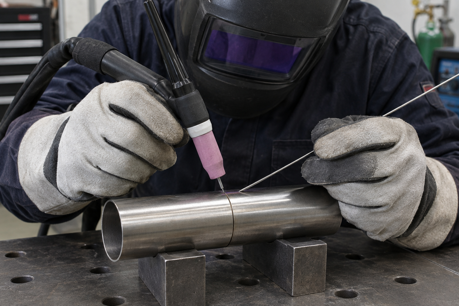
6. Control Accumulated Heat, Not Just Peak Amperage
The first inch of weld and the last inch don’t see the same conditions. As the tube warms up, the same pedal position produces a larger puddle, so you’ll generally need to taper current or adjust travel. Watch puddle width and edge behavior instead of trying to preserve one pedal position. Once the edges start sagging, you’re already behind.
Use pulse as a tool, not a rescue setting
For a slow, rhythmic pulse trial, start around 1–2 pulses per second, 30–40% peak time, and background current at 25–35% of peak. Set peak current high enough to establish fusion, because simply adding pulse to an already marginal setting can produce a cold weld. You can time filler additions with the peak while the background gives the puddle a chance to settle. Pulse definitely has its place, but it won’t repair a gap or an overlong arc.
On a multi-joint assembly, alternate between separated joints or opposing sides rather than pouring all the heat into one corner. Let the work cool naturally between segments when needed, and follow any specified interpass-temperature limit instead of guessing by touch. Copper backing or a fitted chill fixture can help where accessible, but keep copper out of the molten weld. Don’t water-quench the assembly as a shortcut.
7. Diagnose the Weld Before Calling It Finished
A neat outside bead doesn’t prove the joint is fused through or free of internal oxidation. Inspect the inside where possible, looking for incomplete penetration, excessive root protrusion, or sugaring on stainless. Check the outside for undercut, pinholes, crater defects, and obvious lack of fusion at either toe. Weld color alone isn’t an acceptance test.
- Holes at the start: Check the gap, starting-current behavior, and whether the arc is sitting on one unsupported edge.
- Holes near the finish: Reduce current earlier as heat builds and practice a controlled crater fill.
- Ropey bead with poor tie-in: Check for insufficient current, excessive filler, or travel that outruns fusion.
- Gray stainless despite a purge: Check outside shielding, leaks, drafts, excessive stickout, and overheating separately from root shielding.
- Distortion after unclamping: Revisit fit-up, tack sequence, weld sequence, and fixture restraint—not just amperage.
For practice, weld matching offcuts and section the joint or carry out an appropriate destructive test rather than judging only the ripples. Change one variable at a time and record the wall thickness, current limit, filler size, and pulse settings. The useful target is repeatable fusion with controlled reinforcement and an assembly that still fits afterward. Pretty comes second.