
How to TIG Weld Inside Corners and Box Frames Without Pulling Them Out of Square
Inside corners expose every weak spot in your TIG setup: too much tungsten stickout, a torch angle you can’t hold, or a frame that was only square before the first weld. The fix isn’t simply turning down the amperage. You need access to the root, enough heat to fuse both members, and a welding sequence that doesn’t drag the whole assembly toward one corner.
1. Identify the Joint and Fit the Frame Before Welding
An inside corner describes a location, not necessarily a fillet weld. A crossmember meeting a side rail usually creates a fillet joint, while two square tubes cut at 45 degrees create a miter joint with different weld geometry around their faces. That distinction matters because a fillet needs fusion into both members at its root, while a miter needs the specified fusion through the meeting edges. Don’t build a big fillet over a miter seam and assume you’ve fixed poor fit-up.
For thin-wall tubing, aim for close, consistent contact unless the drawing or welding procedure specifies a root opening. An accidental 1/16-inch gap in 0.065-inch-wall tubing is roughly one wall thickness, and it changes the job considerably. Correct the cuts instead of planning to bridge everything with filler. Check the frame on a flat surface before you clamp it.
- Deburr inside and outside edges so the pieces seat properly.
- Remove mill scale, rust, paint, oil, and plating from the weld area; don’t TIG through coatings.
- Check side lengths and both diagonals. Equal diagonals alone don’t prove an arbitrary four-sided assembly is square.
- Check for twist by confirming all corners sit against the same flat reference.
- Provide a vent path for every cavity that could become sealed during welding, following the fabrication plan. Never heat or weld a sealed tube volume.
For a nominal 30-by-30-inch square frame, each outside diagonal should be about 42.43 inches when measured between corresponding outside corners. Matching them within 1/32 inch may be a useful shop target, but the drawing sets the actual tolerance. Check flatness separately. A frame can measure square and still rock on the table.
2. Set Up the TIG Torch for Real Inside-Corner Access
A short back cap and a compact torch head often solve more problems than another 20 amps. Before striking an arc, put the torch in the tightest corner and rehearse the full movement with your gloves on. Include the filler hand, because a torch that fits without room to feed rod doesn’t really fit. Support your hands without putting them where the assembly will soon get hot.
A gas lens is useful because it straightens the shielding flow and allows more usable tungsten extension than a standard collet body in many setups. Start with a #7 or #8 cup and roughly 1/4–3/8 inch of stickout, then verify shielding on scrap with the same corner geometry. Those cup numbers mean a 7/16- or 1/2-inch opening. More stickout isn’t free reach; eventually the electrode tip and puddle move outside reliable coverage.
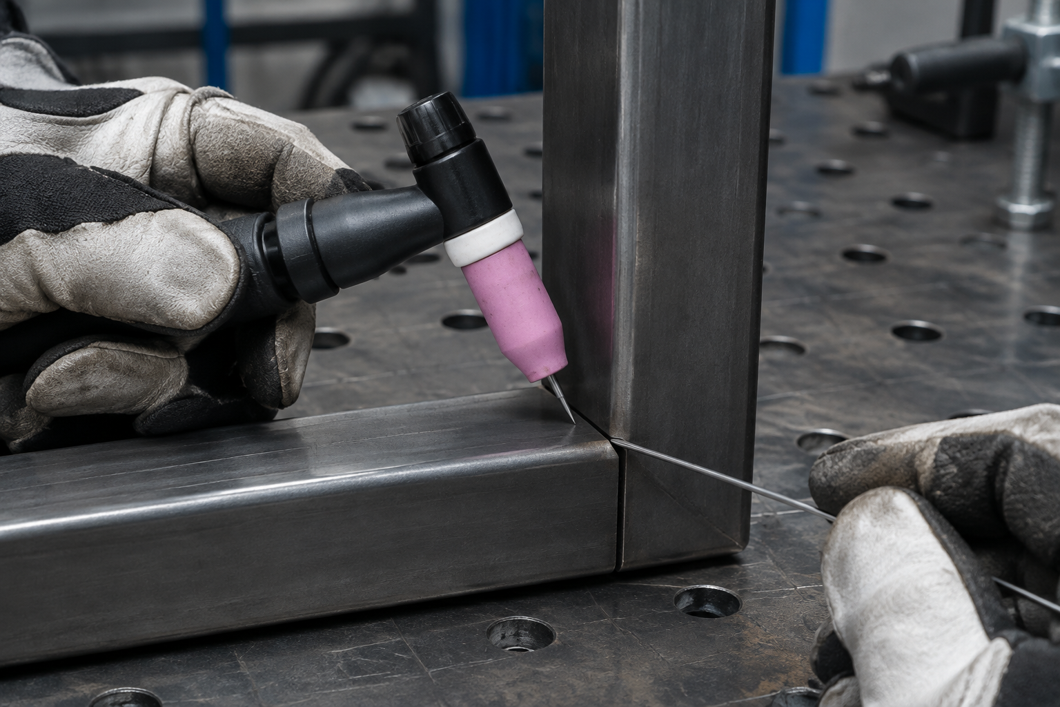
For an equal-thickness 90-degree fillet, start with the torch bisecting the joint at about 45 degrees to each face. Keep the travel angle modest, roughly 5–15 degrees from perpendicular to the direction of travel, and maintain an arc length around 1–2 mm when access allows. Excessive tilt spreads the arc onto one wall and pulls shielding away from the other. Reposition the frame rather than welding the whole corner at a bad angle.
3. Use Starting Settings That Match the Wall Thickness
Set enough available amperage to establish the puddle promptly, then control heat with the pedal or torch control. Creeping up on a cold joint for several seconds heats a larger area and can distort thin tubing before you make useful progress. The ranges below are starting maximum-current settings for clean, close-fitting joints welded in a comfortable position. They aren’t qualified procedures or instructions to hold full pedal through the entire weld.
| Material | Wall thickness | Polarity | Starting maximum current | Typical filler selection |
|---|---|---|---|---|
| Mild steel | 0.065 inch / 1.6 mm | DCEN | 45–75 A | ER70S-2 |
| Mild steel | 0.125 inch / 3.2 mm | DCEN | 100–140 A | ER70S-2 |
| 304L stainless | 0.065 inch / 1.6 mm | DCEN | 35–65 A | ER308L |
| 304L stainless | 0.125 inch / 3.2 mm | DCEN | 80–120 A | ER308L |
| 6061 aluminum | 0.065 inch / 1.6 mm | AC | 65–100 A | ER4043 where suitable for the application |
| 6061 aluminum | 0.125 inch / 3.2 mm | AC | 130–180 A | ER4043 where suitable for the application |
A 3/32-inch lanthanated tungsten covers much of this work, although a 1/16-inch electrode can give good low-current control on thin steel or stainless. Start with 1/16-inch filler for thin tubing and consider 3/32 inch for heavier joints where the puddle accepts it without freezing. Use 100% argon, typically around 15–20 CFH through a #7–#8 cup in still air. Excessive flow can create turbulence, so fix leaks and drafts before cranking up the regulator.
4. Establish Root Fusion Before Building the Bead
Start where you can clearly see both joint faces, not with the electrode buried behind the cup. Hold a short arc and watch for a puddle that wets both members at the root. If one wall melts while the other stays solid, check arc placement and work angle before adding more filler. Rod can cover that problem beautifully without solving it.
Feed the leading edge, not the tungsten
Add filler at the leading edge of the puddle with the rod held low enough to stay under the shielding envelope. Use small additions and advance only as fast as both toes continue wetting into the parent metal. On thin tubing, I’d favor a narrow stringer over a wide weave because spreading the heat usually makes edge control harder. Keep the hot filler tip near the shielding between additions.
- Establish fusion into both faces.
- Add enough filler to support the specified weld profile.
- Advance a short distance while keeping the arc length steady.
- Ease off current as the corner accumulates heat.
- At the stop, taper current and add filler as needed to fill the crater.
Don’t chase a decorative stack of dimes at the expense of fusion. A convex bead with rolled-over toes can indicate cold lap, while undercut means you’ve melted an edge without replacing enough metal. If you touch the tungsten with the filler or puddle, stop and regrind the contaminated portion. Trying to burn it clean in the joint just spreads the trouble.
5. Tack and Sequence the Box Frame to Control Distortion
Weld shrinkage pulls hardest when you keep feeding it from the same direction. Tack all four corners before completing any one joint, and place tacks on opposing faces where access and the joint design allow. On clean 0.065-inch steel tubing, sound tacks around 1/8–1/4 inch long can be a practical starting point, but restraint and joint loading determine what’s sufficient. Remelt those tacks properly into the finished weld.
Move across the frame instead of walking around it
Label the corners A, B, C, and D around the perimeter, then work diagonally: A, C, B, D. Within that pattern, alternate corresponding tube faces rather than completing every face at A before moving on. If outside faces will become inaccessible, account for that before assembly locks you out. The sequence has to suit the part, not just look tidy on paper.
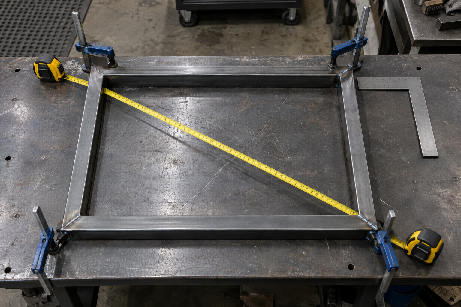
Recheck dimensions after tacking and after the first balanced group of welds. Clamps help maintain position, but a heavily restrained frame can spring when released, so let it cool before the final unclamped inspection. On longer seams, alternate short weld lengths across the assembly while still completing the required weld coverage. Don’t substitute intermittent welds for a specified continuous weld.
6. Adjust for Stainless and Aluminum Corners
Stainless rewards prompt puddle formation, steady travel, and sensible cooling between welds. With 304L, use dedicated abrasives and brushes so you don’t embed carbon-steel contamination. If penetration exposes the backside to oxidation, particularly on sanitary or corrosion-critical work, provide the specified backing purge; the torch’s argon cannot protect the inside of a tube. A shiny face bead doesn’t prove the root is acceptable.
Aluminum needs degreasing followed by oxide removal with a dedicated stainless brush or suitable clean abrasive. For an inverter, 80–120 Hz AC and roughly 65–75% electrode-negative balance are reasonable starting settings on clean material, but check the machine’s balance convention because some displays show cleaning percentage instead. Aluminum takes substantial initial heat, then needs less pedal as the assembly warms. Don’t keep the same pedal position just because the first inch looked good.
Filler selection for aluminum depends on alloy, service temperature, strength requirements, and finishing—not just which rod flows nicely. Also, welding 6061-T6 reduces strength in the heat-affected zone, so a good-looking corner doesn’t restore the original temper. Load-bearing frames need an appropriate design and welding procedure. That’s an engineering issue, not a bead-appearance contest.
7. Troubleshoot the Corner and Inspect the Finished Frame
Use an offcut corner made from the actual tubing to prove your settings before committing to the frame. A straight bead on flat plate won’t reproduce the restricted torch angle or heat flow into two members. For critical work, use the required inspection and procedure qualification rather than judging everything by appearance. A practice fillet that can be sectioned and etched reveals far more about root fusion than surface ripples.
- Arc jumps between walls: Shorten the arc, check the tungsten point, and center it over the root.
- Porosity: Check cleanliness, gas leaks, drafts, excessive flow, and shielding at the actual stickout.
- One toe won’t wet: Correct the work angle and account for unequal member thickness or heat sinking.
- Edges collapse: Reduce current as heat builds, correct excessive gaps, and keep filler additions controlled.
- Crater cracking: Improve downslope and crater filling; don’t snap off the arc and leave a hollow stop.
Inspect the cooled, unclamped frame for dimensions, twist, cracks, undercut, overlap, and missed welds. Use a fillet gauge where a fillet size is specified rather than estimating from bead width. Keep suitable ventilation, PPE, and nonchlorinated cleaning practices part of the setup, especially around enclosed frame spaces. Get the fit-up, access, and sequence right, and the puddle becomes the manageable part.