
How to TIG Weld Cast Aluminum Engine Parts Without Chasing Porosity
A cracked aluminum engine cover can look like a ten-minute weld until the puddle starts bubbling and pushing black crud ahead of the arc. Castings hold oil, coolant, and sometimes porosity from manufacturing, so welding them takes more than turning up the cleaning action. Here’s how to TIG weld cast aluminum engine parts with a repair plan that accounts for contamination, heat, distortion, and whether the part belongs on your bench at all.
1. Decide Whether the Casting Is Worth Welding
A removable timing cover with a cracked flange is a different job from a cylinder head cracked through a valve-seat pocket. Both might be aluminum, but the consequences of distortion or another crack are nowhere near the same. Before grinding, identify the alloy if possible, locate the entire damage, and establish what dimensions must survive the repair. A bead that looks good doesn’t answer any of those questions.
- Reasonable repair candidates: accessible cracks in nonstructural covers, localized oil-pan damage, and some broken mounting ears after checking their loading.
- Specialist work: cylinder heads, combustion-chamber damage, main-bearing supports, and cracks involving bearing bores or highly loaded mounts.
- Possible replacement jobs: widespread cracking, severe corrosion, inaccessible contamination, or damage with no practical inspection or machining route.
Check casting numbers and manufacturer information rather than guessing from color or weight. Some engine and transmission housings are magnesium, and aluminum filler and procedures are not suitable substitutes. Also, a heat-treated casting can lose strength around the weld even when it welds cleanly. If the repair depends on retaining original strength, get an approved procedure or replace the part.
2. Strip and Degrease the Engine Part Before Grinding
Remove the part from the engine and strip seals, bearings, gaskets, sensors, and anything else that cannot tolerate cleaning and heating. Drain trapped passages and remove sludge before bringing the casting anywhere near an arc. Welding an assembled oily housing gives you poor access, hidden contamination, and a fire problem. Put the work clamp directly on clean metal on the part, with no current path through bearings or electronics.
Get the oil out, not just off the surface
Start with an aluminum-compatible aqueous degreaser, rinse as directed, and dry thoroughly, including blind holes. Avoid strongly caustic cleaners unless the process is specifically controlled for aluminum. A suitable nonchlorinated solvent can handle final surface cleaning, but read its safety information and let it evaporate completely before heating. Never use chlorinated brake cleaner around welding; arc radiation and heat can produce highly toxic decomposition products.
- Wash the entire repair area, including the backside and nearby oil galleries.
- Remove paint, gasket residue, sealant, and corrosion at least 1 inch beyond the planned weld where access permits.
- For an oil-soaked casting, use controlled warming in suitable ventilated shop equipment to reveal more oil, then cool to a safe handling temperature and clean again.
- Repeat until fresh oil stops appearing, keeping the heating cycle within the part’s allowable temperature limits.
A controlled warming cycle around 200–250°F (95–120°C) may help expose absorbed oil, but it is not a guaranteed cure for an impregnated casting. Don’t put engine parts in a food oven or heat a solvent-wet part. Use ventilation for cleaning and welding without blowing a draft through your shielding gas. If contamination keeps returning, stop and reassess rather than cooking the part hotter.
3. Find the Crack Ends and Excavate to Sound Metal
Use an aluminum-compatible dye-penetrant system to map the crack before cutting, following its cleaning and inspection instructions. Remove all penetrant and developer afterward because those materials do not belong in the weld. A visible crack often extends farther than the dark line you first noticed. Welding over that line without removing the cracked material just hides the defect.
Use a sharp carbide burr suited to aluminum to open the crack into a groove you can actually reach with the arc and filler. A roughly 60–90-degree included angle is a useful starting geometry, but access and wall thickness determine the final shape. Avoid grinding wheels that load up and smear contamination into the surface. For a through-crack, plan full penetration or access from both sides rather than leaving an unfused root.
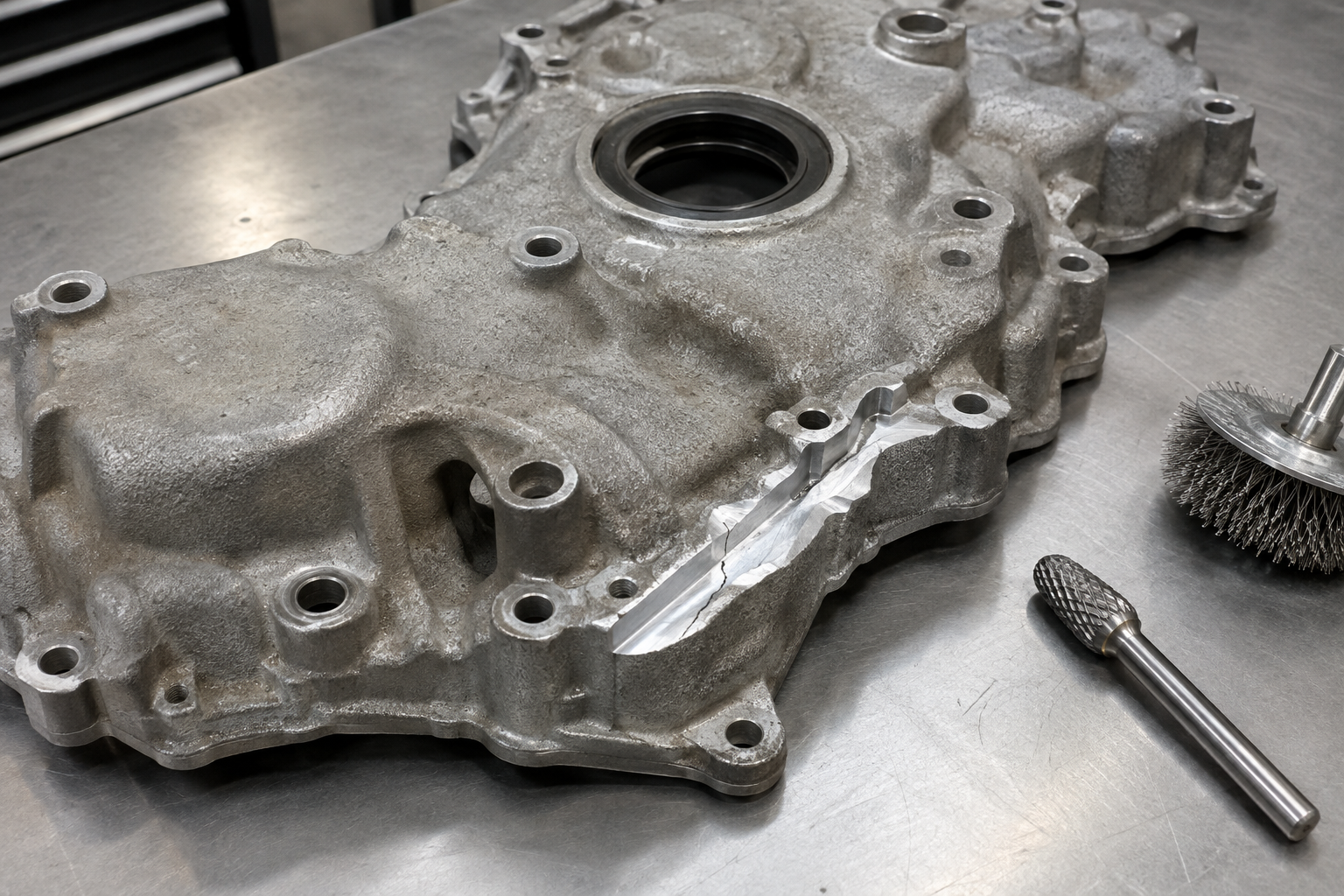
Remove embedded dirt and porous metal until the excavation is sound, then brush with a clean stainless steel brush reserved for aluminum. I prefer doing the final oxide removal shortly before welding, not leaving the prepared casting sitting overnight. If the groove keeps getting wider because every cut exposes another cavity, that is useful information. You may need an engineered insert repair—or another casting.
4. Choose Filler and Set Up the AC TIG Machine
For many common aluminum-silicon engine castings, ER4043 is a practical starting filler because it flows well and resists hot cracking. ER4047 contains more silicon and can help with fluidity and crack resistance in suitable repairs, but it is not a universal upgrade. Match filler to the identified base alloy, operating temperature, and repair requirements. An OEM procedure takes priority over whatever rod happens to be beside the bench.
Don’t automatically reach for ER5356 because you want a “stronger” repair. It is not the default choice for aluminum-silicon castings, and its sustained elevated-temperature service restrictions matter on engine components, particularly above roughly 150°F (65°C). Neither filler selection nor a larger bead restores a casting’s original heat treatment. Those are separate issues.
| Setup item | Practical starting point |
|---|---|
| Polarity | AC TIG with high-frequency starting |
| Shielding gas | 100% argon, approximately 15–20 CFH (7–9.5 L/min) indoors without drafts |
| Cup | #7 or #8, preferably with a gas lens when access allows |
| Tungsten | 3/32-inch (2.4 mm) lanthanated for moderate current; consider 1/8-inch (3.2 mm) for higher-current work |
| AC balance | Start around 70–75% electrode negative on machines displaying EN percentage |
| AC frequency | Approximately 80–120 Hz on an adjustable inverter |
| Filler diameter | 3/32-inch for general repair; 1/16-inch for small edges and 1/8-inch for larger grooves |
Set enough amperage to establish the puddle
As rough pedal-controlled starting ranges, allow about 90–140 amps for a 1/8-inch (3 mm) wall and 160–220 amps for a 1/4-inch (6 mm) section. A heavy boss connected to a large casting may need substantially more current than its local thickness suggests. These are starting ranges, not a welding procedure, because preheat, joint geometry, and surrounding mass change the demand. For sustained high-current work, check the machine’s duty cycle and the torch’s AC rating; a water-cooled torch earns its keep here.
Check how your machine labels balance before adjusting it, because “cleaning percentage” and “EN percentage” move in opposite directions. More electrode-positive time increases oxide cleaning but also heats the tungsten and reduces penetration capability. Use enough cleaning action to control the oxide, not as a substitute for degreasing. On a conventional transformer machine, use its available AC frequency and balance controls rather than chasing inverter settings.
5. Control Preheat and Protect Machined Surfaces
Preheat helps a bulky casting establish a puddle without sitting on the pedal forever, but more heat is not automatically better. For a suitable noncritical repair with no stricter specification, roughly 200–250°F (95–120°C) is a conservative starting range. Follow the alloy or OEM limit where known, and don’t treat 300°F (150°C) as universally harmless. Temperature and time both affect heat-treated material.
Warm the casting evenly with controlled equipment and measure near the repair with a contact probe or suitable temperature indicator. Infrared readings on shiny aluminum can be misleading unless emissivity is accounted for. Record flange flatness and critical dimensions before welding so you have something meaningful to compare afterward. Support the part on a fixture that controls alignment without locking every direction against thermal expansion.
- Keep welding and grinding debris away from oil galleries and bearing surfaces.
- Position tacks to hold fit-up, then recheck alignment before filling the groove.
- Plan short weld lengths and an alternating sequence where geometry allows.
- Monitor interpass temperature; pause before exceeding the repair’s allowable limit.
6. Read the Puddle Instead of Welding Over Contamination
Keep a short arc, roughly 1/8 inch (3 mm) or less where access permits, and use only enough torch angle to see the leading edge. Establish a shiny, controllable puddle that wets both groove faces before adding filler. Feed into the leading edge while keeping the hot rod tip inside the shielding envelope. Excessive torch lean spreads the arc and leaves you chasing heat instead of directing it.
If the puddle bubbles, grows black specks, or refuses to wet, stop rather than burying the mess under more rod. Let the area cool as needed, burr out the contaminated deposit, clean, and try again. Some castings require several excavation-and-cleaning cycles, but persistent porosity is a reason to reject the repair. Turning up AC cleaning cannot remove oil coming from inside the casting.
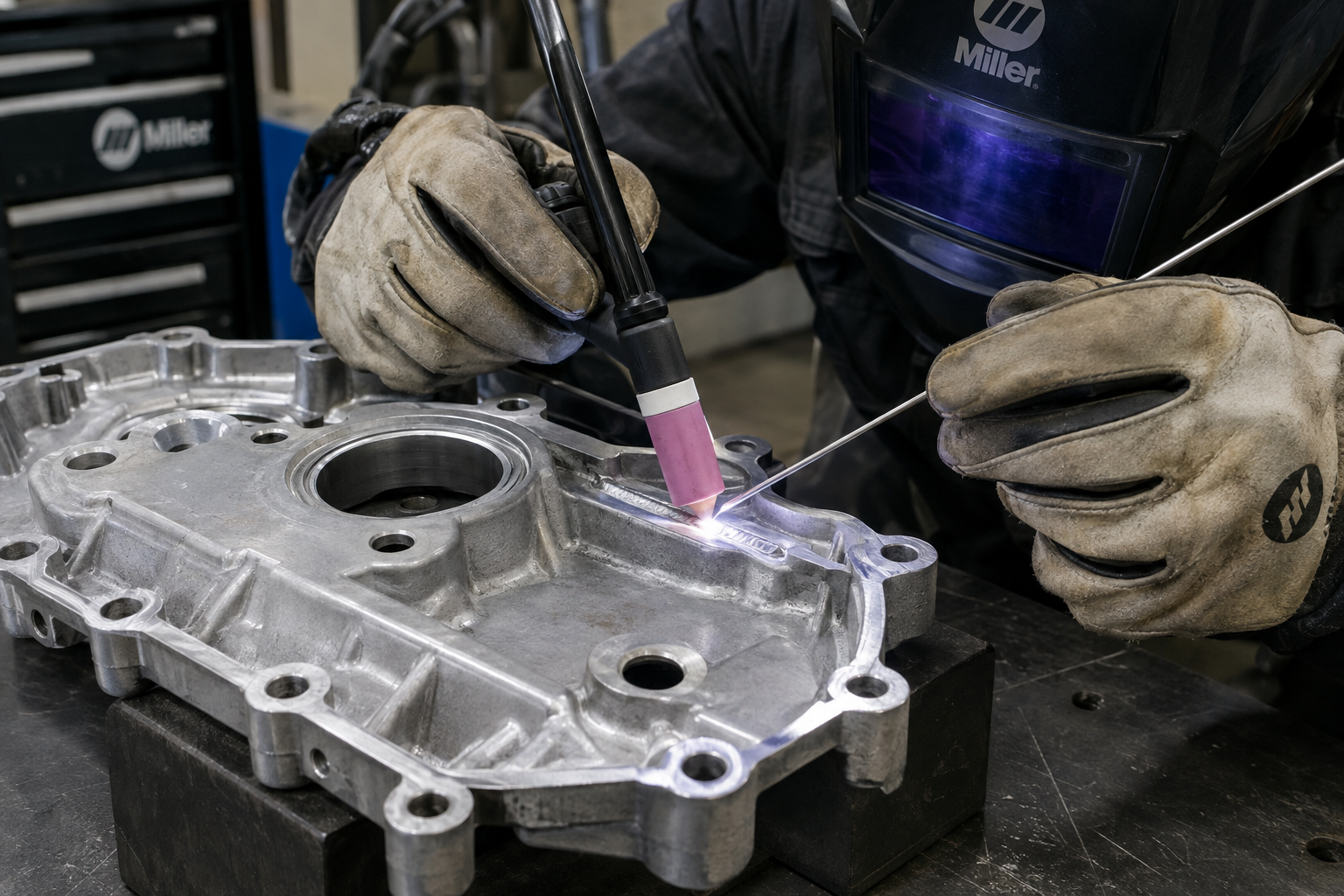
Use narrow stringer beads and add enough filler to fill the groove without building an oversized mound. As the casting heats up, back off the pedal; the current that started the first puddle may collapse a thin edge later. At each stop, taper current while adding a final dab to fill the crater, then hold shielding over it through postflow. Crater cracks are small, but they count.
7. Inspect for Cracks, Leaks, and Distortion
Let the casting cool in still air or according to its specified repair procedure, away from cold drafts. Don’t water-quench it or use compressed air to rush the job. Clean the completed repair and inspect under good lighting before any machining hides the surface. Look for crater cracks, undercut, visible pores, and incomplete fusion along the groove edges.
- Surface integrity: repeat penetrant inspection after cooling and cleaning; it finds surface-breaking defects, not every internal flaw.
- Geometry: check flange flatness, bolt-hole alignment, and nearby bores against service limits.
- Leak tightness: use the component’s specified leak-test method and pressure, with proper fixtures and guarding—not an improvised shop-air setup.
- Final cleanliness: remove chips, abrasive residue, and inspection chemicals from passages before assembly.
A cover may need its gasket face resurfaced, and a repaired threaded boss may need machining before it can carry its intended load. Cylinder heads and other critical castings need specialist inspection beyond a visual check and a leak test. The useful repair is the one that seals, fits, and survives service. A pretty bead is only part of that job.