
How to TIG Weld Aluminum Frames and Brackets Without Pulling Them Out of Square
A square aluminum frame starts moving as soon as you weld the first corner. Add a thick mounting bracket to thin-wall tubing and you’ve also got two pieces that want very different amounts of heat. Here’s how to TIG weld aluminum frames and brackets with settings, fit-up, and a weld sequence that keep the puddle under control—and the finished assembly close to the drawing.
1. Identify the Aluminum Before You Design the Joint
6061-T6 square tubing and plate are common choices for fabricated aluminum frames and mounting brackets. They weld readily, but welding softens the heat-affected zone, so the finished assembly doesn’t retain T6 strength beside the weld. A bigger bead won’t restore that strength, and it can add unnecessary heat and distortion. For load-bearing work, size the members and joints using appropriate welded-material properties.
Know what you’re welding before choosing filler. Some high-strength alloys, including common 2024 and 7075 products, are generally unsuitable for ordinary fusion-welded fabrication. Unknown scrap is a poor starting point for a bracket that holds anything expensive—or anybody. Vehicle suspension parts, lifting attachments, and other safety-critical assemblies need qualified engineering and welding procedures, not just a decent-looking bead.
- 4043 filler: A practical first choice for many 6061 frame joints, with good fluidity and resistance to solidification cracking.
- 5356 filler: Useful where its mechanical properties or closer anodized color match are required, provided it suits the base alloy and service conditions.
- Elevated-temperature service: Don’t default to 5356 for sustained exposure above roughly 150°F (65°C); check the applicable filler-selection guidance.
2. Fit and Clean the Joints Before Turning Up the Amperage
For thin-wall tubing, aim for close, consistent contact rather than leaving a deliberate root gap. On 0.063-inch wall material, even a 1/32-inch opening is substantial, and bridging it can melt back the edges before you establish a useful puddle. Cut miters accurately, deburr inside and out, and check that rounded tube corners aren’t holding a bracket away from its intended contact surfaces. Fix the fit instead of asking the filler rod to become a structural patch.
Use the Right Cleaning Order
Degrease first, then remove the oxide mechanically with a dedicated stainless-steel brush or clean aluminum-specific preparation tool. Brushing oily aluminum first just works the contamination around. Use a suitable nonchlorinated cleaner, let it evaporate completely, and keep solvent containers and vapor away from the welding area. Never use chlorinated brake cleaner around welding.
- Remove paint, anodizing, and other coatings from the weld area and adjacent surfaces.
- Degrease the joint, including accessible backside surfaces that will get hot.
- Brush the joint faces and roughly 1/2–1 inch beside the weld immediately before assembly.
- Keep filler rods clean and handle prepared surfaces with clean gloves.
Hollow frames also need an escape path for heated air. Don’t weld the final closure on a sealed tube cavity without a planned vent, because rising internal pressure can blow through the puddle. Locate vent holes where the design permits, and remember that connected-looking tubes may still contain separate sealed compartments. Check each cavity.
3. Set Up AC TIG for the Tube Wall, Not Just the Bracket
Use AC TIG with high-frequency starting and 100% argon as your baseline. On a modern inverter, I’d start around 100–120 Hz AC frequency and 70–75% electrode negative, then adjust from the test joint. Machine displays differ: some show electrode-negative percentage, while others show cleaning or electrode-positive percentage. Check the manual before copying a balance number, because reversing that interpretation puts a lot more heat into the tungsten.
| Material thickness | Approximate available current | Practical filler diameter |
|---|---|---|
| 1/16 inch (1.6 mm) | 60–90 A | 1/16 inch |
| 3/32 inch (2.4 mm) | 90–130 A | 1/16–3/32 inch |
| 1/8 inch (3.2 mm) | 130–180 A | 3/32 inch |
| 3/16 inch (4.8 mm) | 180–250 A | 3/32–1/8 inch |
These are starting ranges for available current with pedal control, not fixed welding currents or a qualified procedure. A cold inside fillet may need more initial current than an exposed outside corner of the same thickness. For 1/8-inch plate against 0.063-inch tube, test that actual combination rather than choosing settings from the plate thickness alone. Aluminum conducts heat away quickly at the start, then the assembly gets hot and needs less pedal.
- Tungsten: A 3/32-inch, 2% lanthanated electrode suits much light fabrication; consider 1/8 inch toward the upper current range, following machine guidance.
- Tip: Use a lengthwise-ground taper with a small truncated point on compatible inverters; don’t deliberately form a giant ball.
- Shielding: Start with a #7 or #8 cup and about 15–20 CFH argon indoors. Excess flow can create turbulence rather than better coverage.
- Torch: Check its AC amperage rating and duty cycle. Sustained high-current work can justify a water-cooled setup.
4. Tack the Frame Square and Leave Yourself Torch Access
Lay the frame on a flat fixture and measure both diagonals before tacking. For example, a nominal 24-by-36-inch rectangle has diagonals of approximately 43.27 inches, but matching diagonal measurements must accompany correct side lengths and straight members. Clamp enough to hold alignment without forcing badly fitted parts together. Spring-loaded fit-up becomes spring-loaded distortion when you release the clamps.
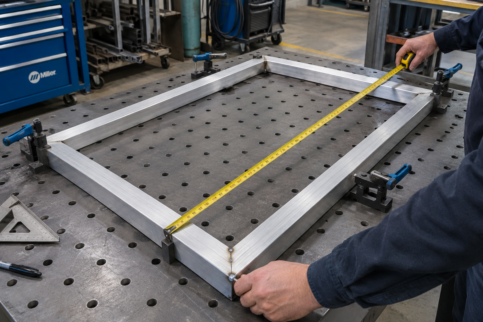
Place small, sound tacks on opposing faces where accessible, alternating between opposite corners instead of finishing one corner first. Tack every joint before committing to full welds, then recheck dimensions and rocking on the table. A cracked or porous tack needs removal, not burial under the finish bead. If it remains part of the weld, it needs to be sound.
- Make a dry torch pass with gloves on and the filler rod in position.
- Move clamps that block the cup, your sightline, or the filler approach.
- Use stops or spacers to locate brackets, but protect precision threads from arc damage.
- Keep the work-return connection on clean metal with a reliable current path.
5. Control the Puddle Where Thick Brackets Meet Thin Tubing
Keep a short arc, roughly 1/16–1/8 inch where access allows, and use only enough torch tilt to see and feed the puddle. A long arc spreads heat, makes placement less precise, and leaves you chasing a wider puddle. Establish fusion promptly rather than hovering at low current while the surrounding tube gets hot. Once both members are wetting, add filler at the leading edge and move.
Bias the Heat Toward the Heavy Member
With a 1/8-inch bracket on 0.063-inch tube, direct more arc energy into the bracket and let the puddle wash onto the tube. Watch the thin-side edge closely: it should melt into the joint, not curl away ahead of you. Add filler to build the fillet, but don’t use oversized rod to repeatedly freeze a puddle that hasn’t fused at the root. That’s how a substantial-looking bead ends up sitting on the surface.
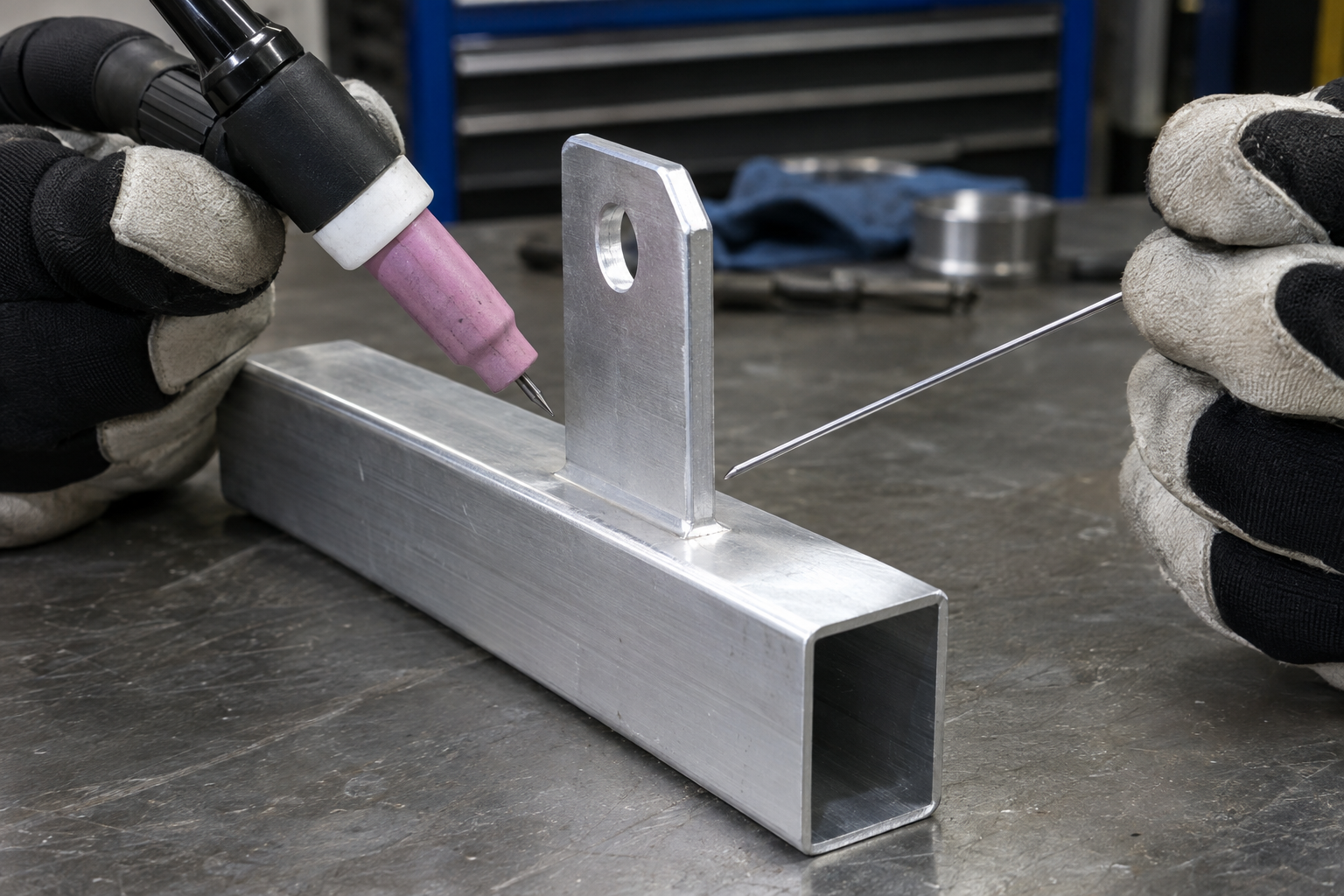
Keep the hot filler tip inside the shielding envelope, and stop if you dip the tungsten. Regrind the electrode and remove contaminated weld metal before restarting; trying to burn through the mess usually makes more mess. As the assembly warms, reduce pedal input while maintaining controlled travel and the required bead size. At the stop, taper the current and add filler to leave a filled crater rather than a sharp depression.
6. Sequence the Welds to Limit Pull and Twist
Finish-welding one corner before touching the others is an easy way to pull a frame out of square. Weld contraction acts locally, so balance your sequence around the assembly instead of concentrating it in one area. On a rectangular frame, move between diagonally opposite corners and alternate opposing faces where practical. Recheck the frame between stages, not after every joint is locked solid.
- Weld one accessible joint segment at the first corner.
- Move to the diagonally opposite corner for a comparable segment.
- Work the remaining two corners, then alternate faces.
- Sequence bracket welds across the assembly rather than completing every weld at one location.
- Allow natural cooling as needed and inspect dimensions before continuing.
For longer seams, short, balanced runs can help, but don’t turn a required continuous weld into intermittent welds without design approval. Excessive stops also create more opportunities for crater cracks and poor tie-ins. Avoid oversizing fillets: extra weld metal means extra contraction, not automatically a better bracket. Weld to the specified size.
Don’t use a water quench as a shortcut for controlling frame temperature. Let the assembly cool naturally, and use consistent measurement conditions because a hot frame is larger than a cold one. Preheat usually isn’t necessary for light tubing and brackets, and blanket heating can make thin-wall control worse. If heavy sections require preheat, follow an alloy-appropriate procedure with measured temperature limits.
7. Inspect Fusion, Craters, and Final Alignment
Inspect after cooling and releasing the fixture, because clamps can hide distortion. Check diagonals, flatness, bracket spacing, and bolt-hole alignment against the drawing. Then inspect weld toes, starts, and stops for cracks, undercut, visible porosity, and unfilled craters. A neat stack of dimes isn’t proof of root fusion.
- Black specks or dirty puddle: Check surface preparation, filler cleanliness, shielding coverage, leaks, and tungsten contamination.
- Rounded bead with poor wetting: Check for inadequate heat, excessive filler, oxide, or poor arc placement.
- Thin-wall edge melting away: Shorten the arc, favor the thicker part, and reduce heat as the assembly warms.
- Crater crack: Remove the defect and repair using a controlled downslope and adequate crater fill.
For a new joint combination, make a representative coupon before welding the frame. Sectioning and examining a practice fillet can expose lack of fusion that the surface hides, although critical work requires the specified inspection and qualification methods. Record the alloy, thicknesses, filler, settings, and sequence that produced an acceptable result. The useful result is a sound joint and a frame that fits—not just a photographable bead.