TIG Welding 4130: Chromoly Tubing | TIG Welding Secrets
How to TIG Weld Chromoly Tubing: 7 Steps for Clean Thin-Wall 4130 Joints
Thin-wall 4130 doesn’t give you much room to hide a poor fit-up. A gap that looks harmless on the bench becomes a hole when the tube gets hot, and adding more filler won’t fix an edge that never fused. Learning how to TIG weld chromoly tubing is mostly about controlling fit-up, arc placement, and accumulated heat—not finding one magic amperage setting.
This walkthrough covers clean, normalized 4130 tubing, primarily 0.035–0.065 inch wall, joined in the as-welded condition. It isn’t a procedure for every roll cage, aircraft fuselage, or suspension component. For safety-critical work, the drawing, applicable rules, and qualified procedure control the material, filler, heat treatment, and inspection requirements.
1. Confirm the 4130 Tubing and Plan the Joint
Start with the material specification, not somebody’s description of “chrome-moly.” Confirm the alloy, wall thickness, and supplied condition; normalized 4130 and quenched-and-tempered 4130 aren’t interchangeable starting points. Measure the actual wall on an offcut, especially if the tubing came from an unmarked rack. You can’t select a sensible procedure from outside diameter alone.
4130 is a chromium-molybdenum low-alloy steel, and its heat-affected zone can harden depending on the material and thermal cycle. Thin, normalized tubing is commonly joined without elevated preheat under suitable procedures, but that doesn’t mean every 4130 assembly needs the same treatment. Thicker fittings, heavy restraint, cold material, or different delivery conditions change the situation. Don’t transfer thin-tube advice to a thick machined suspension boss.
- Check access: Can you reach the entire joint with the torch and filler after assembly?
- Plan ventilation: Don’t weld a completely sealed tube cavity; provide an approved vent path before the closing weld.
- Prepare safely: Use suitable eye, skin, and respiratory protection, local fume extraction that doesn’t disturb shielding, and a secured argon cylinder.
- Make coupons: Save matching tubing for practice joints using the same wall, joint angle, and position.
2. Cope the Tube Closely and Clean Both Sides
A close fishmouth fit makes thin-wall chromoly much easier to join because both edges enter the puddle together. I’d spend extra time at the notcher before trying to rescue a loose joint with the pedal. Aim for consistent contact around a coped tube rather than a deliberate root opening, unless the specified joint design requires one. On 0.035-inch wall, a 0.020-inch gap is already more than half the material thickness.
Deburr the cope without thinning its sharp tips, then remove mill scale, oxide, oil, paint, and marker residue from the joint area. Clean roughly 1/2–1 inch back from the joint, including the accessible inside surface near the cut edge. Use a suitable nonchlorinated cleaner and let it evaporate completely before striking an arc. Never use chlorinated brake cleaner around the arc; radiation and heat can produce highly toxic decomposition products.
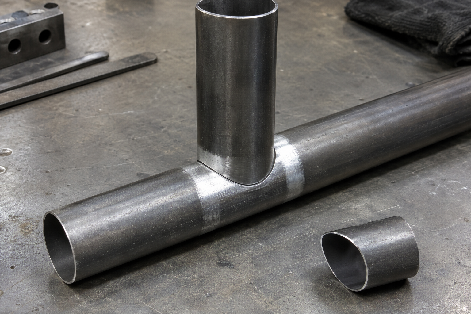
Don’t leave grinding grit inside the tube and call the outside clean enough. Blow out or otherwise remove loose debris safely, then handle the cleaned area with clean gloves. Wipe the filler rod too, especially if it has been sitting exposed on the bench. Clean, clean, clean—but don’t grind away the wall you’re trying to join.
3. Choose Filler for the Design, Not Just the Alloy Name
ER70S-2 is a common filler choice for normalized thin-wall 4130 assemblies that remain as welded, where the design and procedure permit it. Its ductility and deoxidizers make it useful, but it is an undermatching choice relative to many 4130 base-metal conditions. That means joint strength still has to be addressed by the design and procedure. “Everybody uses it” isn’t an engineering calculation.
- ER70S-2: A common option for appropriate as-welded thin-tube fabrication.
- ER80S-D2: A higher-strength alternative when specified; don’t assume it automatically makes the assembly better.
- Matching 4130 filler: Typically selected as part of a procedure addressing the intended mechanical properties and heat treatment, not simply because the tube says 4130.
For 0.035–0.049-inch wall, 0.035- or 0.045-inch filler gives you manageable additions without chilling a tiny puddle excessively. A 1/16-inch rod is useful on 0.058–0.065-inch wall and larger fillets, although smaller wire still works when the required deposit is modest. I’d choose the smallest rod that supplies enough metal without frantic feeding. Don’t substitute stainless filler as a shortcut unless the application specifically calls for it.
4. Set Up DCEN TIG and Establish an Amperage Window
Use DC electrode negative, 100% argon, and a clean, sharply ground tungsten. A 1/16-inch 2% lanthanated tungsten is a practical starting point across these wall thicknesses; 3/32 inch also works if it’s prepared properly and your machine starts cleanly at low current. Grind lengthwise to a consistent taper with a tiny flat rather than a fragile needle point. A wandering arc makes it harder to keep heat off the thin cope tips.
Starting Settings for Thin-Wall 4130
These are coupon starting ranges for close-fitting tube joints, not qualified production settings. Set the machine ceiling toward the upper end and use a pedal or suitable remote control to meter current as the joint heats. Tube diameter, position, joint angle, and a thicker mating member can move the useful range considerably. Don’t expect a tube-to-plate joint to behave like two equal-wall tubes.
| Tube wall | Initial current window | Useful filler diameter |
|---|---|---|
| 0.035 in. / 0.9 mm | 30–50 A | 0.035–0.045 in. |
| 0.049 in. / 1.2 mm | 40–65 A | 0.045–1/16 in. |
| 0.058 in. / 1.5 mm | 45–75 A | 0.045–1/16 in. |
| 0.065 in. / 1.7 mm | 50–85 A | 1/16 in. |
- Cup: A #6–#8 gas-lens cup is a useful starting combination.
- Argon flow: Start around 12–18 CFH indoors and verify coverage. Excess flow can draw air into turbulent shielding.
- Tungsten stickout: Start around 1/8–3/16 inch; longer reach needs suitable coverage and testing.
- Gas timing: Roughly 0.3–0.5 second preflow and 5–8 seconds postflow are reasonable initial settings at these currents.
I’d leave pulse off until the basic joint is repeatable. Pulse can help establish a feeding rhythm, but it won’t correct poor fit-up or a long arc. If you try it, document peak current, background current, frequency, and peak-time percentage together. A frequency number by itself tells you very little.
5. Tack Securely and Control Starting Temperature
Fixture the tubes without forcing a badly fitted joint into place. Put small, fully fused tacks around the circumference—often four spaced locations on a simple T-joint—and recheck alignment before joining the sections. Tack sequence matters because the first tack can pull the opposite side open. Add filler where needed, and remove cracked or contaminated tacks rather than burying them.
For clean, normalized thin-wall 4130, many established procedures do not require elevated preheat when the material is dry and at a suitable shop temperature. That is different from striking an arc on tubing brought in from a freezing yard. Follow the procedure’s minimum temperature, preheat, and maximum interpass requirements, and verify temperature with suitable equipment. Don’t guess from how long you can touch it.
Arrange the work so you can rotate it or reposition yourself between sections. A comfortable two-inch run beats a heroic trip around the back with the cup hitting the fixture. Plan the order to distribute shrinkage, particularly on multi-tube clusters. The fixture helps hold alignment, but it doesn’t make distortion disappear.
6. Weld Short Sections with a Tight Arc
Start where you can see both members, establish a small puddle, and add filler once both sides are melting. Hold roughly a 1/16-inch arc length or slightly less when access allows, with about 5–15 degrees of torch tilt from perpendicular. Direct the arc so it catches both joint surfaces instead of washing filler over one cold side. At thin cope tips, bias heat away from the vulnerable edge while still achieving fusion.
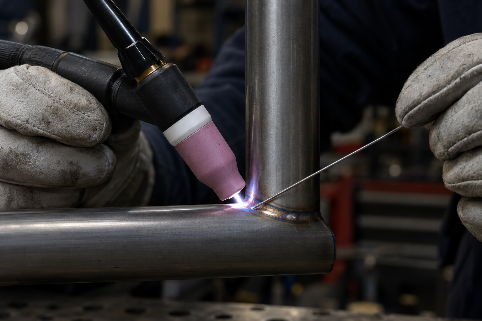
Add small dabs at the leading edge, move forward, and reduce current as heat builds. On a small-diameter tube, the pedal position that started the pass may be too much halfway around. Work in manageable sections, often about 1/2–1 inch where access requires, but avoid unnecessary starts and stops. You want steady progress, not prolonged heating at low current while waiting for the joint to cooperate.
Stop Before the Puddle Drops Out
If the puddle suddenly widens or the edge starts retreating, back off and stop under shielding before you create a hole. At a normal stop, taper current while adding a final small amount of filler to leave a filled crater. Keep the torch over the finish during postflow, then inspect the stop before restarting. Restart on sound metal and carry the puddle through the tie-in rather than leaving a cold overlap.
- Tungsten touched the puddle: Stop and regrind it; address any suspected tungsten inclusion.
- Filler balls up: Check arc length and feed position; the rod may be melting before it reaches the puddle.
- Black, porous deposit: Check cleanliness, shielding leaks, drafts, and torch angle before continuing.
7. Cool Naturally, Inspect, and Validate the Technique
Let the assembly cool in still air unless the specified procedure requires another cooling method. Don’t water-quench it or blast the hot joint with compressed air. Likewise, don’t apply an improvised torch “stress relief”; controlled postweld heat treatment requires defined temperatures, holding times, and heating and cooling practices. A guessed color isn’t a heat-treatment schedule.
Inspect the entire circumference under good light, using a mirror where necessary. Look for cracks, undercut, surface porosity, unfilled craters, overlap, and missed areas behind tube clusters. Check the internal root on coupons where accessible; back purging isn’t universally required for these joints, but the procedure and root-quality requirements may call for it. Bead color and evenly spaced ripples don’t prove fusion.
Before committing to a critical assembly, section representative practice joints and evaluate fusion, root condition, and remaining wall thickness. Formal qualification and any required nondestructive testing belong with appropriately qualified personnel. Record the successful fit-up, filler, settings, and sequence so the next joint isn’t another experiment. That’s the useful goal: repeatable fusion without sacrificing the thin tube beside the joint.