How To Fix Common TIG Weld Defects
How to Fix Common TIG Weld Defects
Know the Variables: Why TIG Weld Defects Happen
TIG, or GTAW, is prized for precision—but that precision means the process is highly sensitive to small changes. Most defects trace back to a few controllable variables: cleanliness, heat input, arc length, shielding gas coverage, and joint fit-up. When any of these slip, porosity, lack of fusion, undercut, cracks, and inclusions can appear. Understanding how each variable affects the molten puddle helps you pinpoint root causes faster and correct technique or settings confidently.
Start by standardizing your setup: dedicated brushes and solvents for each alloy, leak-free gas delivery, and correctly prepared tungsten. Keep arc length short (about one electrode diameter), maintain a steady travel speed, and avoid overheating the workpiece. If problems arise, change only one variable at a time while observing the puddle. Controlled experimentation narrows the root cause and prevents chasing your tail.
Porosity in TIG Welds: Causes and Cures
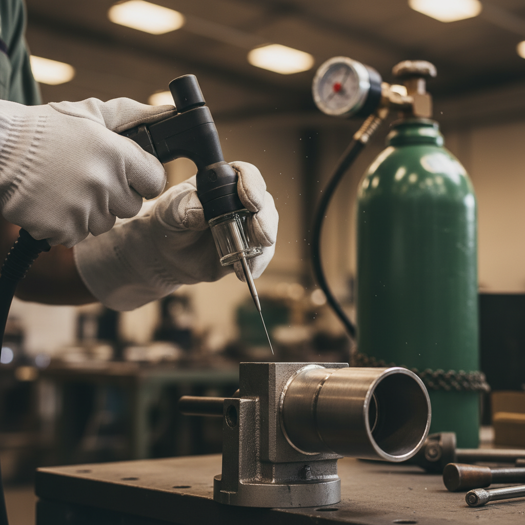
Porosity—those tiny gas pockets trapped in the weld metal—comes from contamination or insufficient shielding. Moisture, oil, paint, oxides, and even fingerprints can release gas as the puddle solidifies. Excessive gas flow can also create turbulence, entraining air into the shielding envelope. On aluminum, the oxide layer and residual hydrocarbons are frequent culprits, while on stainless, poor purging or drafts often lead to pores, especially on open roots.
Fixing porosity starts with uncompromising cleanliness and stable shielding. Mechanically remove oxides, then degrease with a suitable solvent just before welding. Verify your argon purity, eliminate leaks at fittings and the torch, and set an appropriate flow rate (typically 15–25 CFH with a gas lens, adjusted for cup size and draft). For aluminum, dial AC balance to achieve sufficient cleaning action without overheating the puddle.
Shielding Gas and Contamination Checklist
- Use dedicated stainless, carbon steel, and aluminum wire brushes to avoid cross-contamination.
- Wipe joints and filler rods with acetone or alcohol; store filler in sealed tubes to reduce moisture pickup.
- Install a gas lens and a larger cup (#8–#12) for better coverage; set 15–25 CFH and avoid blasting the joint.
- Check for leaks with soapy water, inspect O-rings, and use a gas saver lens for out-of-position work.
- For roots and tubing, back purge until oxygen is controlled; maintain purge through cooldown to prevent sugaring.
- On aluminum, stainless, or titanium, preheat thick sections to chase off moisture, not to compensate for poor technique.
Lack of Fusion and Cold Lap: Getting the Puddle to Wet In
Lack of fusion occurs when the weld metal does not bond to the base metal or the previous pass, often due to low heat input, excessive travel speed, or a long arc length. Cold lap (or overlap) happens when the filler piles up without fusing at the toes, usually from a shallow puddle and low energy density. Both show up prominently on fillets and lap joints, especially on thicker materials or when welding out of position. The cure is better energy placement, tighter arc control, and deliberate sidewall wetting.
Set amperage to match thickness—roughly 1 amp per thousandth of an inch as a starting point for carbon steel and stainless (adjust down with pulse). Shorten the arc to increase energy density, and hold a 10–15 degree torch push angle. Pause slightly at each toe to let the puddle wash in before advancing. If the joint is tight or the oxide layer is stubborn, increase AC frequency (for aluminum) or bevel the joint to ensure access to the root.
Technique Drill: Etch and Inspect
- Run a short practice bead with your chosen settings.
- Cross-section and etch the bead with a mild acid or nital (following safety procedures).
- Inspect for toe fusion and root penetration; adjust amperage, arc length, and travel speed accordingly.
- Repeat until toes are blended with smooth transition and no cold lap waves are visible.
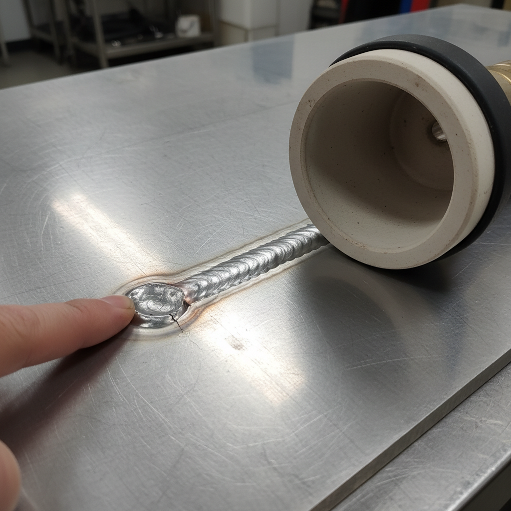
Cracks and Crater Issues: Preventing Hot Cracking and Shrinkage Damage
Cracks fall into categories: hot cracking (during solidification), cold cracking (delayed), and crater cracking (at the weld end). Hot cracks often stem from high restraint, inappropriate filler chemistry, or excessive heat that widens the mushy zone. Crater cracks develop when the arc stops abruptly and the crater shrinks without adequate filler support. These defects compromise integrity and can be hard to detect without thorough inspection.
To prevent cracks, match filler metal to the base alloy and service conditions; some aluminum joints benefit from 4xxx filler to reduce hot cracking. Use a crater fill function or manually ramp down current while adding a touch of filler to support the shrinking puddle. Limit heat input by managing interpass temperature and allowing adequate cooling between beads. On hardenable or high-carbon steels, controlled preheat and slow cooling mitigate cold cracking from hydrogen and residual stress.
Filler Metal and Preheat Choices
- Select fillers that counter cracking tendencies (e.g., ER4043 for many aluminum applications, nickel-bearing fillers for certain stainless tasks).
- Preheat medium/high-carbon steels according to thickness to reduce thermal gradients; maintain interpass temperature.
- Use stringer beads instead of wide weaves, especially on sensitive alloys.
- Terminate with a slight back-step and filler addition to support the crater before slope-down.
Tungsten Inclusion and Arc Wander: Electrode Preparation Done Right
Tungsten inclusions show up when the electrode contacts the puddle or spalls due to overheating and contamination. Arc wander typically stems from poor tip geometry, improper grind direction, magnetic interference, or unbalanced gas flow. A consistently prepared electrode focuses the arc and stabilizes the puddle, reducing the risk of inclusions and erratic bead profiles. Proper storage and dedicated grinding practices are essential, especially for critical stainless and titanium work.
Grind tungsten lengthwise (parallel to the electrode) on a dedicated, clean wheel to produce axial grind lines that focus the arc. For most work, 2% lanthanated tungsten performs well; point for DC with a truncated tip, and allow a modest hemisphere on AC aluminum if your machine does not support stable pointed AC. Keep stick-out short—typically 3–6 mm with a gas lens—and avoid overheating by setting proper preflow and postflow. If you dip the tungsten, stop, break off the contaminated section, and regrind before continuing.
- Use a gas lens for smoother, laminar flow that stabilizes the arc and reduces wander.
- Maintain torch angle at 10–15 degrees to prevent shielding disruption.
- Match electrode diameter to current (e.g., 1/16 in up to ~100 A, 3/32 in for higher currents).
- Keep cables straight to reduce magnetic arc blow on DC ferrous work.
Undercut, Excess Reinforcement, and Bead Profile Control
Undercut occurs when the arc erodes the toe of the weld without refilling it, leaving a groove that reduces fatigue strength. Excess reinforcement and ropey beads come from depositing too much filler or traveling too slowly with a narrow, high crown. Good bead profile requires balanced heat, proper filler size, and a torch angle that favors edge wetting without washing out the toes. The goal is a smooth transition with slight convexity or near-flush for butt joints.
Keep the arc short and aim energy slightly ahead of the puddle’s leading edge. Hold a stable 10–15 degree push angle and add filler on the front edge, not the center, to help the toes wet in. Choose filler diameter that matches current and pace; too large a rod chills the puddle and causes piling. Pulse can help: high-frequency pulse focuses the arc and reduces heat input while improving edge definition on thin sections.
- Set travel speed so the puddle width is 2–3 times electrode diameter for most fillets.
- Use micro-pauses at the toes; avoid dwelling too long in the center.
- Select a slightly smaller filler when fighting ropey beads; increase travel speed modestly.
- On aluminum, increase AC frequency (100–200 Hz) for a tighter arc cone to protect toes.
Discoloration, Heat Tint, and Oxidation on Stainless and Titanium
Heat tint on stainless ranges from light straw to deep blue and gray; darker colors indicate higher oxidation and reduced corrosion resistance. Titanium is even more sensitive—any straw, purple, or blue hues mean inadequate shielding, and gray/white chalkiness indicates severe contamination. These defects stem from inadequate trailing gas, poor postflow, insufficient purge on roots, or excessive heat input. Minimizing oxygen exposure until the weld cools below oxidation temperature is critical.
Improve shielding by using a large cup with a gas lens (#12 or larger) and increase postflow (10–20 seconds, longer for larger tungsten). For titanium and thin stainless tubing, employ trailing shields and keep the torch moving to maintain coverage. Back purge enclosed volumes, tape and dam ends, and monitor oxygen content if possible to ensure consistent results. Reduce heat input through proper amperage, faster travel, and pulse to prevent overheating that accelerates oxidation.
- Back purge stainless and titanium roots; aim for oxygen below the threshold for sugaring (visual confirmation or O2 meter when available).
- Keep filler within the gas envelope; do not preheat filler in open air.
- Avoid touching hot metal with bare gloves that can shed contaminants into the puddle.
- Clean oxide on aluminum mechanically and weld promptly to limit re-oxidation.
Distortion and Heat Control: Keeping Parts Straight
Even with perfect fusion, excessive distortion can render a weld unusable. TIG’s focused arc reduces heat compared to some processes, but thin sections and long joints still pull as the metal contracts. Distortion often indicates uneven heat input, poor fixturing, or suboptimal sequencing rather than a fundamental TIG limitation. Control it by balancing welds, limiting dwell time, and using fixtures and heat sinks strategically.
Tack frequently, spaced evenly, and size tacks to match the weld profile. Use copper or aluminum backing bars to draw heat out of thin parts, and clamp joints to rigid fixtures when tolerances are tight. Sequence welds to balance shrinkage—use skip welding patterns or alternate sides on symmetrical parts. If you can, break long seams into shorter segments and let them cool between passes.
Using Pulse to Control Heat Input
- Training and rhythm: 1–2 Hz, 30–50% peak time, base current ~30–50% of peak. Add filler on peaks.
- Heat control on thin stainless: 30–100 Hz, peak current ~70–90% of non-pulsed value, base current ~30–40% to keep the arc lit without overheating.
- Arc focusing for aluminum edges: 100–200 Hz with higher AC frequency for a tighter cone and reduced wash.
- Use slope-up and slope-down to avoid crater defects and to ramp heat smoothly.
Quick Diagnostic Flow: From Symptom to Solution
When a defect appears, respond methodically rather than changing everything at once. Observe the puddle, bead edges, and arc behavior, and correlate symptoms to likely root causes. A short diagnostic pass can save hours of rework, especially on sensitive alloys. Use the following flow to structure your troubleshooting.
- Porosity visible or audible popping: verify cleaning, reduce turbulence, check gas purity and flow, improve purge/trailing shield.
- Cold lap or lack of fusion: shorten arc, increase amperage slightly, slow travel at toes, adjust joint prep or AC frequency.
- Undercut: reduce travel speed marginally, adjust torch angle, add filler at leading edge, consider pulse for toe control.
- Crater cracks: add filler while ramping down, enable crater fill, manage interpass temperature.
- Tungsten inclusions/arc wander: regrind electrode longitudinally, shorten stick-out, install gas lens, verify cable routing.
- Heat tint/oxidation: increase postflow and cup size, use trailing shield, back purge effectively, lower heat input.
Mastering TIG is about repetition, observation, and disciplined control of variables. By linking each defect to root causes—shielding, cleanliness, heat input, technique, and fit-up—you can correct problems quickly and build procedures that prevent them altogether. Document your settings, consumables, and prep steps so you can reproduce success across materials and positions. With a consistent approach, cleaner beads and fewer defects become the norm, not the exception.